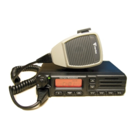
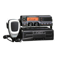
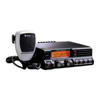
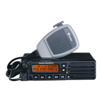
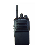
8VX-351PMR446 Service Manual
Alignment
Introduction
The VX-351PMR446 has been aligned at the factory for the
specified performance across the entire frequency range spec-
ified. Realignment should therefore not be necessary except in
the event of a component failure. All component replacement
and service should be performed only by an authorized Vertex
Standard representative, or the warranty policy may be voided.
The following procedures cover the sometimes critical and te-
dious adjustments that are not normally required once the trans-
ceiver has left the factory. However, if damage occurs and some
parts are replaced, realignment may be required. If a sudden
problem occurs during normal operation, it is likely due to com-
ponent failure; realignment should not be done until after the
faulty component has been replaced.
We recommend that servicing be performed only by authorized
Vertex Standard service technicians who are experienced with
the circuitry and fully equipped for repair and alignment. There-
fore, if a fault is suspected, contact the dealer from whom the
transceiver was purchased for instructions regarding repair.
Authorized Vertex Standard service technicians realign all cir-
cuits and make complete performance checks to ensure com-
pliance with factory specifications after replacing any faulty
components. Those who do undertake any of the following
alignments are cautioned to proceed at their own risk. Prob-
lems caused by unauthorized attempts at realignment are not
covered by the warranty policy. Also, Vertex Standard must
reserve the right to change circuits and alignment procedures
in the interest of improved performance, without notifying own-
ers. Under no circumstances should any alignment be attempt-
ed unless the normal function and operation of the transceiver
are clearly understood, the cause of the malfunction has been
clearly pinpointed and any faulty components replaced, and
the need for realignment determined to be absolutely neces-
sary. The following test equipment (and thorough familiarity
with its correct use) is necessary for complete realignment. Cor-
rection of problems caused by misalignment resulting from use
of improper test equipment is not covered under the warranty
policy. While most steps do not require all of the equipment
listed, the interactions of some adjustments may require that
more complex adjustments be performed afterwards. Do not
attempt to perform only a single step unless it is clearly isolat-
ed electrically from all other steps. Have all test equipment ready
before beginning, and follow all of the steps in a section in the
order presented.
Required Test Equipment
Radio Tester with calibrated output level at 600 MHz
In-line Wattmeter with 5% accuracy at 600 MHz
50-ohm, 10 W RF Dummy Load
Regulated DC Power Supply (standard 7.5 VDC, 3 A)
Frequency Counter: ±0.2 ppm accuracy at 600 MHz
AF Signal Generator (available to output 30 Hz to 5 kHz)
AC Voltmeter
DC Voltmeter
UHF Sampling Coupler
Microsoft
®
Windows
®
XP, Windows
®
2000, or Windows
®
Vista Operating System.
Vertex Standard CE95 Alignment program and CT-42 Con-
nection Cable or FIF-12 USB Programming Interface and
CT-106 PC Programming Cable.
Alignment Preparation & Precautions
The VX-351PMR446 can not connect the test equipment to
the antenna directly, because the VX-351PMR446 does not
disconnect the antenna.
When perform the adjustment, connect the test equipment to
the VX-351PMR446 in the following procedure:
1. Remove the Front Panel (refer to the “Exploded View”).
2. Disconnect the solder jumper from JP1001 on the MAIN
Unit (or JP3001 on the MAIN-2 Unit).
3. Connect the TMP connector or coaxial cable to TP1005
(TP3005) (Signal) and TP1006 (TP3006) (GND), then
connect the test equipment to the TMP connector or
coaxial cable.
Note: Do not forget to install the solder jumper to JP1001
(JP3001) after completing the adjustment.
After completing one step, read the following step to deter-
mine whether the same test equipment will be required. If not,
remove the test equipment (except dummy load and wattmeter,
if connected) before proceeding.
Correct alignment requires that the ambient temperature be the
same as that of the transceiver and test equipment, and that this
temperature be held constant between 20 °C and 30 °C. When
the transceiver is brought into the shop from hot or cold air, it
should be allowed time to come to room temperature before
alignment.
Whenever possible, alignments should be made with oscillator
shields and circuit boards firmly affixed in place. Also, the test
equipment must be thoroughly warmed up before beginning.
Note: Signal levels in dB referred to in this procedure are based
on 0 dBμ EMF = 1.0 μV.
 Loading...