9VX-351PMR446 Service Manual
Alignment
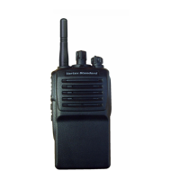
Test Setup
Setup the test equipment as shown for transceiver alignment,
then apply 7.5 V DC power to the transceiver.
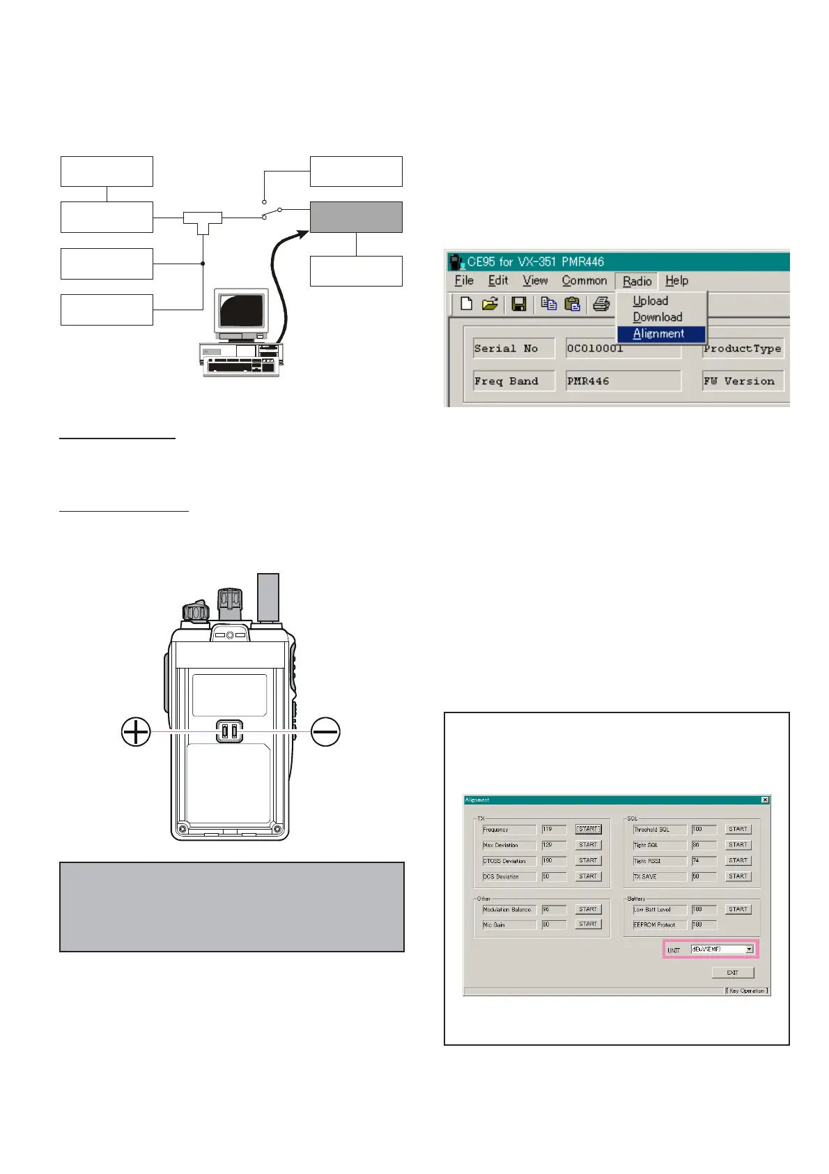
Basic Alignment Mode
The Basic Alignment mode allows you to align the entire ra-
dio. The value of each parameter can be changed to the desired
position by use of the “” / “” keys, along with direct num-
ber input and dragging of the PC mouse.
To enter the Basic Alignment Mode, select “Basic Alignment”
in the main “Radio” menu. It will start to “Upload” the written
personalized data from the radio.
The Alignment Tool Outline
Installation the tool
Install the CE95 (Clone Editor) to your PC.
The re-alignment for VX-351PMR446 may use the
“Alignment” menu of CE95.
Action of the switches
When the transceiver is in alignment mode, the action of PTT
and KEY is ignored. All of the action is remote controlled by
PC.
Note: when all items are to be aligned, it is strongly recom-
mended to align them according to following sequence.
When the item is selected with TAB key, and the F1 key is
pushed, the “Help” file is displayed.
Detailed information for each step may be found in the “Help”
file within CE95 (Clone Editor).
1. PLL Reference Frequency (Frequency)
2. Maximum Deviation
3. Sub Audio Deviation <CTCSS & DCS>
4. Squelch Level
<Threshold, Tight, Thight RSSI, & TX Saver>
5. Modulation Balance
6. Microphone Gain
7. Battery Indicator
Unit
During alignment, you may select the value among
dBμV(EMF), dBμV(PD), μV(EMF), μV(PD), or dBm
from the pull down list.
Caution!
Please never turn off a power supply while alignment.
If the power supply turn off while alignment, the setting
data is failed.
When perform the RX Tune and SQL alignment, the RF
level shows this unit according to this setting.
Transceiver
Inline
Wattmeter
Power Supply
7.5 VDC
Deviation Meter
Frequency
Counter
RF
Signal Generator
50-ohm
Dummy Load
MIC/SP
COM Port
(
for CT-42
)
or
USB Port
(
for FIF-12 + CT-106
)
ANT
RF Sampling
Coupler
BATTERY
TERMINAL
CT-42
or
FIF-12 + CT-106
 Loading...