©2010 VERTEX STANDARD CO., LTD. EC050N90F (USA)
Service Manual
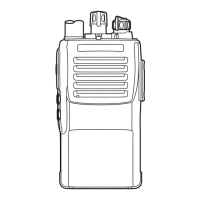
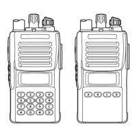
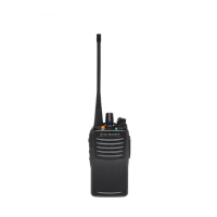
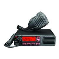
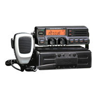
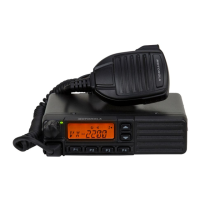
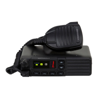
VX-410/-420 series
VHF FM Transceiver
VX-410 series VX-420 series
Introduction
This manual provides technical information necessary
for servicing the VX-410/-420 series FM Transceiver.
Servicing this equipment requires expertise in handling
surface-mount chip components. Attempts by non-quali-
fied persons to service this equipment may result in per-
manent damage not covered by the warranty, and may be
illegal in some countries.
Two PCB layout diagrams are provided for each dou-
ble-sided circuit board in the transceiver. Each side of is
referred to by the type of the majority of components in-
stalled on that side (“leaded” or “chip-only”). In most cases
one side has only chip components, and the other has ei-
ther a mixture of both chip and leaded components (trim-
mers, coils, electrolytic capacitors, ICs, etc.), or leaded
components only.
While we believe the technical information in this man-
ual to be correct, VERTEX STANDARD assumes no lia-
bility for damage that may occur as a result of typograph-
ical or other errors that may be present. Your cooperation
in pointing out any inconsistencies in the technical infor-
mation would be appreciated.
Operating Manual Reprint ...................................2
Cloning .....................................................................7
Specifications ..........................................................8
Exploded View & Miscellaneous Parts ..............9
Block Diagram .......................................................11
Circuit Description ...............................................13
Alignment ..............................................................15
Contents
Board Unit (
Schematics, Layouts & Parts
)
MAIN Unit ............................................................... 19
DUMMY Unit .......................................................... 56
Optional Units (
Schematics, Layouts & Parts
)
FVP-25 Encryption / DTMF Pager Unit .............. 57
VTP-50 VX-Trunk Unit .......................................... 59
DVS-5 Voice Storage Unit ..................................... 61
Important Note
After Lot.36 of this transceiver was assembled using Pb (lead) free solder, based on the RoHS specification.
Only lead-free solder (Alloy Composition: Sn-3.0Ag-0.5Cu) should be used for repairs performed on this apparatus.
The solder stated above utilizes the alloy composition required for compliance with the lead-free specification, and
any solder with the above alloy composition may be used.
VERTEX STANDARD CO., LTD.
4-8-8 Nakameguro, Meguro-Ku, Tokyo 153-8644, Japan
VERTEX STANDARD
US Headquarters
10900 Walker Street, Cypress, CA 90630, U.S.A.
YAESU UK LTD.
Unit 12, Sun Valley Business Park, Winnall Close
Winchester, Hampshire, SO23 0LB, U.K.
VERTEX STANDARD HK LTD.
Unit 5, 20/F., Seaview Centre, 139-141 Hoi Bun Road,
Kwun Tong, Kowloon, Hong Kong
VERTEX STANDARD
(
AUSTRALIA
)
PTY., LTD.
Normanby Business Park, Unit 14/45 Normanby Road
Notting Hill 3168, Victoria, Australia