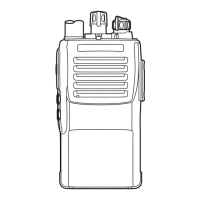
18
Alignment
CTCSS Deviation
U Set the transceiver to CH 2 (band center).
U To adjustment, click the left mouse button on the
“
CTCSS ModulationCTCSS Modulation
CTCSS ModulationCTCSS Modulation
CTCSS Modulation” box, then press the
[
ENTER
]
key to open the pop-up window.
U Use the
[
]
or
[
]
arrow keys so that the deviation
meter reading is ±0.8 kHz (±0.1 kHz) (for 25 kHz steps)
or ±0.5 kHz (±0.1 kHz) (for 12.5 kHz steps) deviation.
U Press the “OK” box to lock in the new data.
MAX Ref Deviation
U Set the transceiver to CH 2 (band center).
U To adjustment, click the left mouse button on the “
MAXMAX
MAXMAX
MAX
Ref Ref
Ref Ref
Ref
DeviationDeviation
DeviationDeviation
Deviation” box, then press the
[
ENTER
]
key to
open the pop-up window.
U Use the
[
]
or
[
]
arrow keys so that the deviation
meter reading is ±0.5 kHz (±0.1 kHz) (for 25 kHz steps)
or ±0.4 kHz (±0.1 kHz) (for 12.5 kHz steps) deviation.
U Set the transceiver to CH 2 (band center), then key the
transmitter, and confirm that the deviation is ±0.6 kHz
~ ±0.9 kHz (for 25 kHz steps) or ±0.35 kHz ~ ±0.6
kHz (for 12.5 kHz steps).
U Press the “OK” box to lock in the new data.
STD Deviation
U Set the transceiver to CH 2 (band center).
U Inject a 1 kHz tone at –37 dBm to the MIC jack.
DTMF Deviation
U Set the transceiver to CH 2 (band center).
U To adjustment, click the left mouse button on the
“
DTMF DeviationDTMF Deviation
DTMF DeviationDTMF Deviation
DTMF Deviation” box, then press the
[
ENTER
]
key
to open the pop-up window.
U Use the
[
]
or
[
]
arrow keys so that the deviation
meter reading is ±3.0 kHz (±0.1 kHz) (for 25 kHz steps)
or ±1.5 kHz (±0.1 kHz) (for 12.5 kHz steps) deviation.
U Press the “OK” box to lock in the new data.
DCS Deviation
U Set the transceiver to CH 2 (band center).
U To adjustment, click the left mouse button on the “
DCSDCS
DCSDCS
DCS
ModulationModulation
ModulationModulation
Modulation” box, then press the
[
ENTER
]
key to open
the pop-up window.
U Use the
[
]
or
[
]
arrow keys so that the deviation
meter reading is ±0.7 kHz (±0.1 kHz) (for 25 kHz steps)
or ±0.45 kHz (±0.1 kHz) (for 12.5 kHz steps) devia-
tion.
U Press the “OK” box to lock in the new data.
Sensitivity
U Set the transceiver to CH 3 (high band edge).
U Tune the RF signal generator to the same frequency as
the transceiver’s, then set the generator output level to
40 dBµ with ±3.0 kHz deviation @ 1 kHz tone modu-
lation.
U To adjustment, click the left mouse button on the “
RXRX
RXRX
RX
SensitivitySensitivity
SensitivitySensitivity
Sensitivity” box, then press the
[
ENTER
]
key to open
the pop-up window.
U Use the
[
]
or
[
]
arrow keys to tune for best sensi-
tivity; ultimately, the radio should be aligned so that
the RF signal generator output level is –6 dBµ EMF
(0.25 µV) or less for 12 dB SINAD.
U Press the “OK” box to lock in the new data.
This completes the internal alignment routine. To save all
settings and exit, press the “OK” box.
U To adjustment, click the left mouse button on the “
MICMIC
MICMIC
MIC
SensitivitySensitivity
SensitivitySensitivity
Sensitivity” box, then press the
[
ENTER
]
key to open
the pop-up window.
U Use the
[
]
or
[
]
arrow keys so that the deviation
meter reading is ±3.0 kHz (±0.1 kHz) (for 25 kHz steps)
or ±1.5 kHz (±0.1 kHz) (for 12.5 kHz steps) deviation.
U Press the “OK” box to lock in the new data.
 Loading...