Page 30
VP-X Installation and Operating Manual
Rev. D (August 5, 2020)
5.9 Alternator Wiring
The VP-X supports a single or dual alternator system. There are several
types of alternators that are common among homebuilders, and each is
shown in detail below. If your specic alternator or voltage regulator is not
listed below, use the directions that came with it – it should be similar to the
wiring described here. Or give us a call.
The VP-X does NOT replace the voltage regulator. Externally-regulated
alternators require a voltage regulator.
The VP-X provides bus voltage (positive) power to the alternator eld input
or voltage regulator from J12 pin 11. This pin is congurable and you set its
circuit breaker value up to 5 amps and assign it to be controlled by any of the
switch inputs (or be always on). When the specied switch input is grounded
by the alternator eld switch, then J12-11 turns on. It works the same as the
other power circuits with the following special considerations:
1. J12-11 turns off if there is an over-voltage condition and
“overvoltage” is shown on EFIS display on the Alternator circuit.
2. If a secondary alternator is congured then only one alternator can
be turned on a time. If one alternator is turned on when the other is
on, then the most recent one to turn on remains on and the other is
shut off, regardless of switch position.
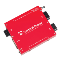
The general wiring scheme for an alternator is shown below, and specic
drawings are shown in the following sections.
J12-11 Switch Input
F
ALT
VP-X
Alt Field
Switch
Correct way to wire alternator eld and eld switch
Do not wire the alternator eld switch as shown below:
J12-11
F
ALT
VP-X
Alt Field
Switch
INCORRECT way to wire the alternator eld switch.
The VP-X thinks the alternator is always on and therefore the synoptic
and the device list on the EFIS are displayed incorrectly.
The wiring diagrams below show the use of 20 AWG wire for the alternator
eld circuit. The VP-X wiring harness use 18 AWG wire. The larger wire
provides a bit more resilience in the harsh environment of the engine
compartment. Electrically, though, either size wire is appropriate.
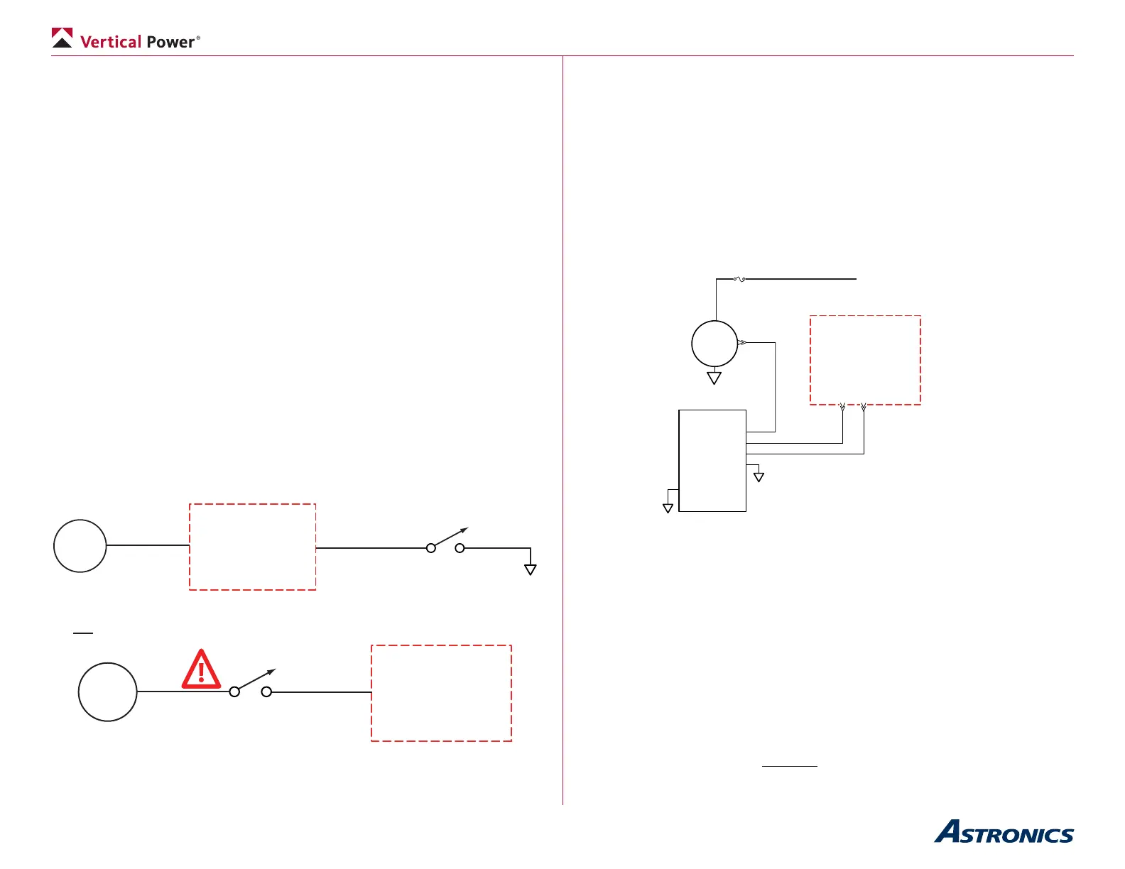
5.9a Primary Alternator (B&C External Regulator)
The B&C LR-3C voltage regulator can be used with several of the B&C
alternators and other externally-regulated alternators. Do not use the SB1B
regulator. The LR-3C requires a power wire for the eld as well as a power
wire for the voltage sense wire, which senses the bus voltage in order to
correctly regulate bus voltage. This diagram shows the alternator wiring:
F
20AWG
J12-11 2A
22AWG
20AWG
B&C LR-3
Volt Reg
VP-X
Pin
FLD 4
Bus 6
V Sense 3
GND 7
B&C
ALT
B
ANL
To PPS B-lead post, or
alternatively, the switched
side of battery contactor
Note: ANL is a type of fuse available in various high-current ratings.
It requires a mounting base and the fuse itself. Try a web search
for “ANL fuse” or go to www.bandc.com
• Run a wire from any 2A, 3A or 5A circuit to pin 3 on the LR-3C.
• Set the circuit breaker value to 2A later when congured.
• Run a wire from the Primary Alt circuit (J12-11) to pin 6 on the LR-
3C.
• Set the circuit breaker value to 5A later when congured.
• Run a wire from pin 4 on the LR-3C to the eld input on the
alternator.
• Ground the LR-3C as per B&C installation manual.
• Run the B-lead wire from the alternator to an ANL fuse on the
rewall, then to the switched side of the battery contactor. The
switched side is the large post on the opposite side of the contactor
from the large post connected to the battery. The B-lead is typically a
6 or 8 AWG wire.