Page 40
VP-X Installation and Operating Manual
Rev. D (August 5, 2020)
5.20 Flap System Wiring
The VP-X controls the aps and provides circuitry for the ap position sensor.
The aps can be congured to run either:
1. Momentary – aps only run when the ap switch is pressed. A
position sensor is optional.
2. Position – aps run down to the next position when the ap switch
is pressed. Flaps run all the way up when the ap switch is pressed.
A ap position sensor (Ray Allen POS-12) is required for this option.
You can set 4 positions – a top, two middle (optional), and a bottom.
When you press the ap up switch, the aps go all the way up unless
you press the ap down switch to stop them mid-stream. On some
aircraft, you can set the reex position to the top position, the 0 deg
position to the rst stop, approach aps to the second stop, and
landing aps to the bottom stop.
If you are setting the ap circuit breaker value to greater than
5 amps, you must have a VP-X with serial number 1350
or higher – Contact Vertical Power Support if you need an
upgrade.
As of rmware version 1.5 the VP-X also supports RV-10 reex settings. In
order to use the reex settings you must have the aps in Position mode as
described above. No special wiring is required to use the reex features. See
“10.5 Trim and ap operation” on page 68 for details on reex operation.
Flap Position Sensor (optional)
Function VP-X Pin I/O
Position feedback (wht/grn) J1-17 I
Ground (wht/org) J1-18 --
+2.5 reference voltage (wht/blu) J1-19 O
Flap Motor and Switch Inputs
Function VP-X Pin I/O
Flap motor J12-5 (connect either way) O
Flap motor J12-6 (connect either way) O
Flap Up switch input J2-14 I
Flap Down switch input J2-15 I
You can wire a ap switch for the pilot and, optionally, one for the co-pilot.
The ap switch must be an SPDT momentary action switch (ON)-OFF-
(ON), with a middle OFF position. Many ap switches also come as DPDT
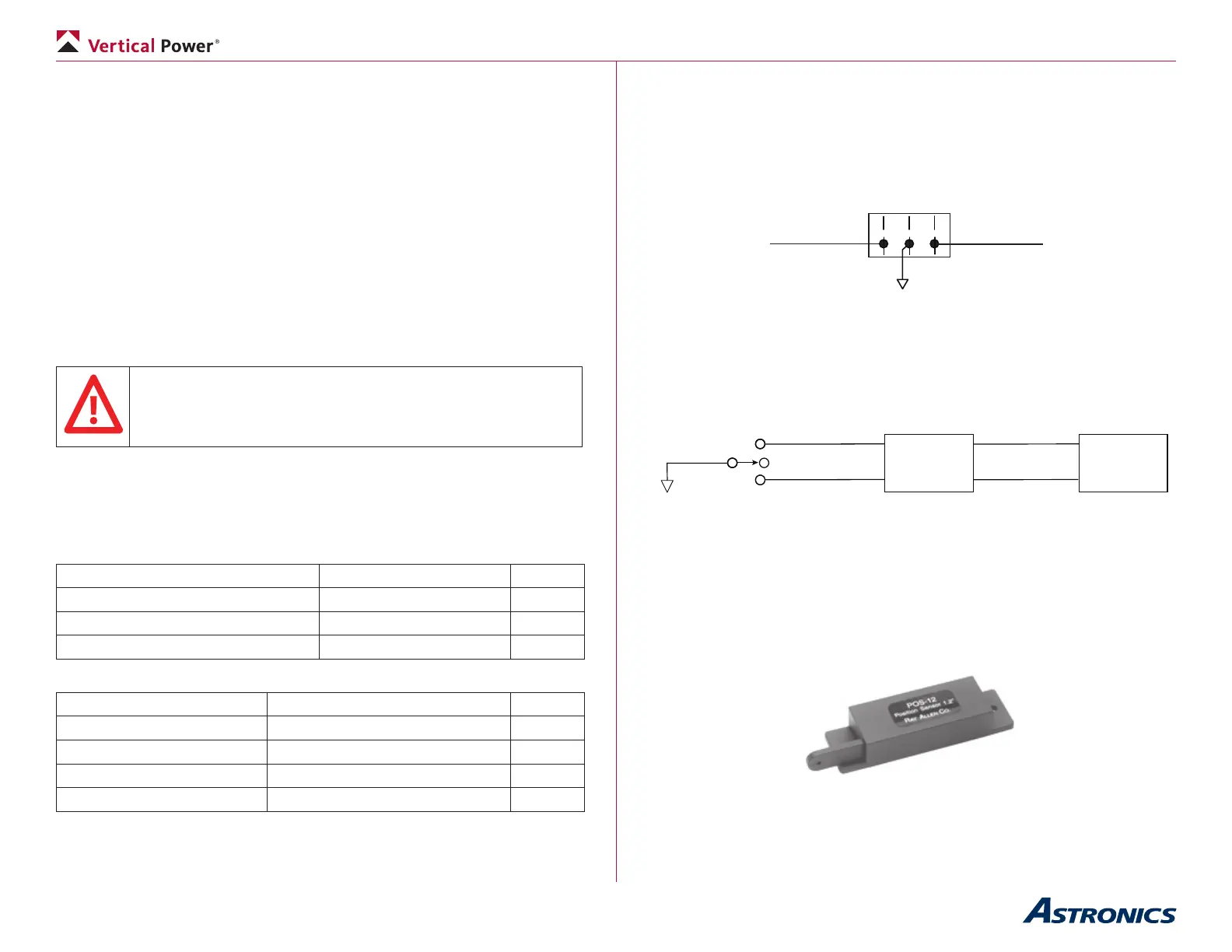
switches. If you have a DPDT switch, you can wire it as shown in the diagram
below:
To Flap Up
switch input
J2-14
(on)-off-(on)
DPDT Flap Switch
To Flap Down
switch input
J2-15
To Gnd
Only three terminals on one side of the switch need to be used.
(Switch viewed from back)
Do not install a ap switch that stays in the UP position.
The ap switch has three pins: a common, one to command aps up and one
to command aps down.
Ground
Flap Motor
VP-X
Flap Switch
(on) - off - (on)
Both ap motor pins on the VP-X (J12, pins 5 & 6) are wired directly to the
ap motor. The polarity of the wires does not matter, as it can be reversed in
the setup menus.
RV ap system: Do not install the Van’s Flap Positioning System (FPS).
If you want intermediate stops or ap position feedback on the EFIS, install a
Ray Allen POS-12 position sensor.
Flap Position Sensor
You can purchase a clevis/pushrod kit from your local hobby shop, as the
Ray Allen kit is not for use with the POS-12.