Page 44
VP-X Installation and Operating Manual
Rev. D (August 5, 2020)
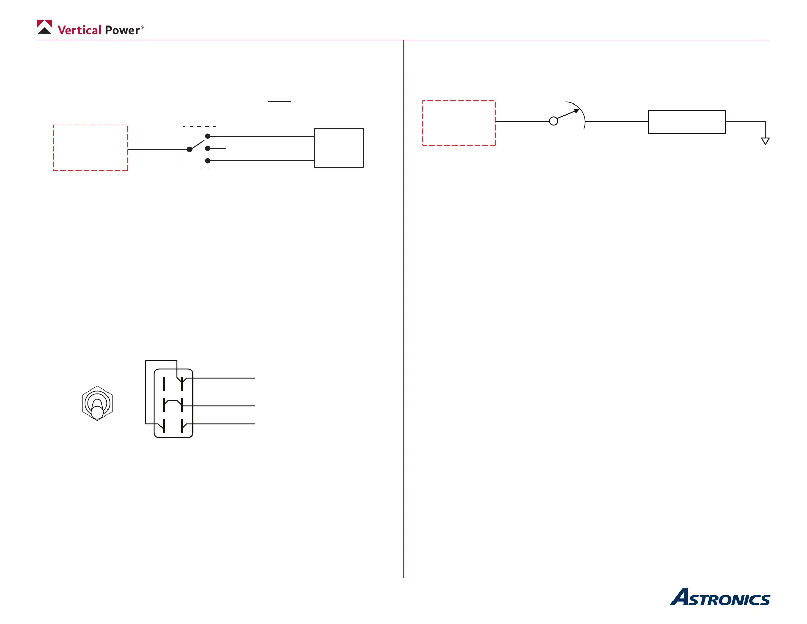
not accidentally turn on in ight. A DUAL SPEED BOOST PUMP MUST BE
WIRED AS SHOWN BELOW:
Use a single power pin set to “always on” and then wire the switch in-line
between the VP-X and the boost pump. The switch does have to be rated to
carry the current load of the pump.
VP-X
Low Boost
Power Pin
Boost Pump
Switch
High Boost
OFF
Boost
Pump
Dual-Speed Boost Pump Wiring
• Wire the boost pump switch.
5.21e Dual-Function Switch
Sometimes you’ll want to wire a switch where the bottom position turns on
a device, the middle is off, and the top position turns on two devices. An
example is a switch that turns on nav and strobe lights. The example shown
here demonstrates the basic idea and you can modify this as needed for your
particular application.
Nav
Nav + Strobe
Front View
DPDT
ON-OFF-ON
Switch
Back View
Nav switch input
To ground
Strobe switch input
Wiring a Dual-Function Switch
5.21f Dimmer wiring
Wire the dimmer in-line between the VP-X and the device, such as a load.
Ensure the rheostat is sized appropriately for the electrical load.
5.21g Mag switch wiring
The mag switch, which is wired to the p-lead on the magneto or electronic
ignition, is separate from the VP-X. Follow the ignition manufacturer’s
instructions for wiring.
• Wire the mag switch.
5.22 P-Mag wiring
The p-leads (pin 4) on the P-Mag are wired to the mag switch, allowing you
to disable the ignition as part of the run up checks. You may also want to
disconnect power individually to each p-mag to test the power-off operation
during run-up (you are testing the unit’s ability to generate its own power). Wire
the P-Mag to one of the power connectors and set the circuit breaker value to
3 amps. (Yes, the P-Mag manual says to use a 2 amp circuit breaker but there
are some cases that drive the need for a 3 amp circuit breaker).
There are three options to power the p-mag(s). The examples below show
dual P-Mags but the same wiring applies to a single P-Mag installation. Wire
power to the P-Mags using one of the three examples below:
1. Wire the power directly from the VP-X to the p-mags. Set the pin on
the VP-X to “Always On” (using the congurator on your laptop). Use
the VP-X page on the EFIS to turn power off then back on to this
circuit when you are testing the P-Mag. The EFIS allows you to turn
power on and off to devices individually right from the screen, and is
primarily meant to be used as a backup to the regular switches.