Page 35
VP-X Installation and Operating Manual
Rev. D (August 5, 2020)
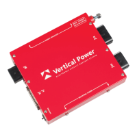
The diagram below shows wiring diagram detail using 20-24 AWG
3-conductor shielded wire (included in wiring harness kit).
Solder sleeve
or
heat shrink
1.5 in max
24 AWG wire,
soldered to shielding
under heat shrink
Shielding (single conductor shown)
VP-XSV PFD
1
20
21
22
Port 2 RX 5
Port 2 TX 6
37-Pin
SV MFD
X
X
Port 2 TX 6
Port 2 RX 5
21
22
1
20
37-Pin
J1-20 TX
J12-9
Power
Ground
Any 5 amp
circuit
J1-22 RX
J1-21 Ser GND
Power
Ground
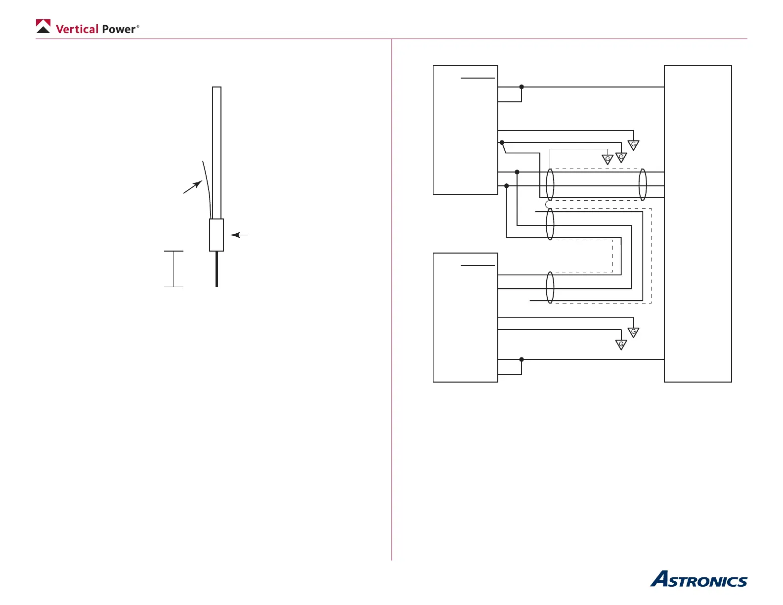
Dynon SkyView Wiring Detail
Wire grounds in locations shown.
(Port 2 shown for example)
Notes on SkyView installation:
• TX = transmit port, RX = receive port, GND = ground.
• Use any open serial port pair on SkyView.
• Use any GND pin 21-24 on SkyView.
• Use 3 conductor shielded wire. Solder wires together within d-sub
hood and cover with heat shrink. Run single wire into d-sub pin.
• The SkyView has two power pins on the display. These two power
pins are simply to spread the load of a single power input across two
power pins. These two power inputs must be soldered together into