Chapter 4 Operator Control And Display Panel 27
APM 300 Integrated UPS Single Module And Parallel System User Manual
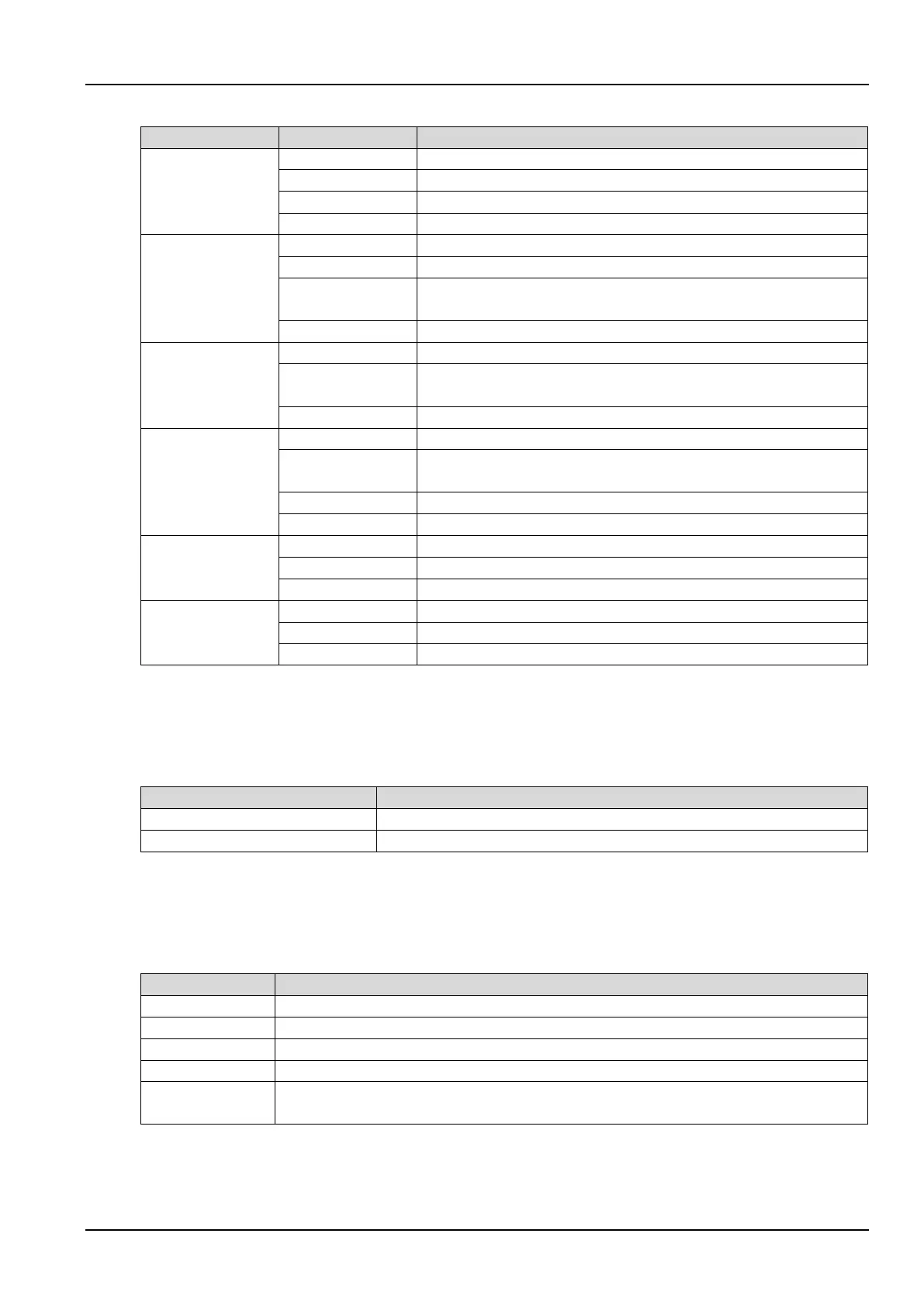
Table 4-2 Description of indicators
Rectifier indicator
Rectifiers in normal operation
Mains input normal, but rectifiers not operating
Rectifiers not operating, mains input abnormal
Battery indicator
Solid red
Battery abnormal (failed, absent or polarity reversed) or battery
converter abnormal (failed, overcurrent or overtemperature)
Battery and battery converter normal, battery charging
Bypass indicator
Solid red
Bypass power abnormal or outside specifications, or static bypass switch
fault
Inverter indicator
Flashing green
Inverters turning on, starting up, synchronizing, or standing by (ECO
mode)
Load indicator
UPS output on and overloaded
Status indicator
Alarm (for example, AC input failure)
Fault (for example, fuse or hardware fault)
4.1.2 Audible Alarm (Buzzer)
UPS activity is accompanied by the two kinds of sound listed in Table 4-3.
Table 4-3 Description of audible alarm
A UPS alarm (for example, AC input failure) took place
A UPS fault (for example, fuse or hardware fault) took place
4.1.3 Control Keys
The operator control and display panel provides five control keys, as described in Table 4-4.
Table 4-4 Description of control keys
Cut off the load power, shut down the rectifier, inverter, static bypass and battery
Restart the UPS (subject to any fault being cleared)
SILENCE ON/OFF
When an alarm is active, pressing this key silences the audible alarm. Pressing this key again
enables the buzzer again



 To Next Page