28 Chapter 4 Operator Control And Display Panel
APM 300 Integrated UPS Single Module And Parallel System User Manual
4.1.4 LCD And Menu Keys
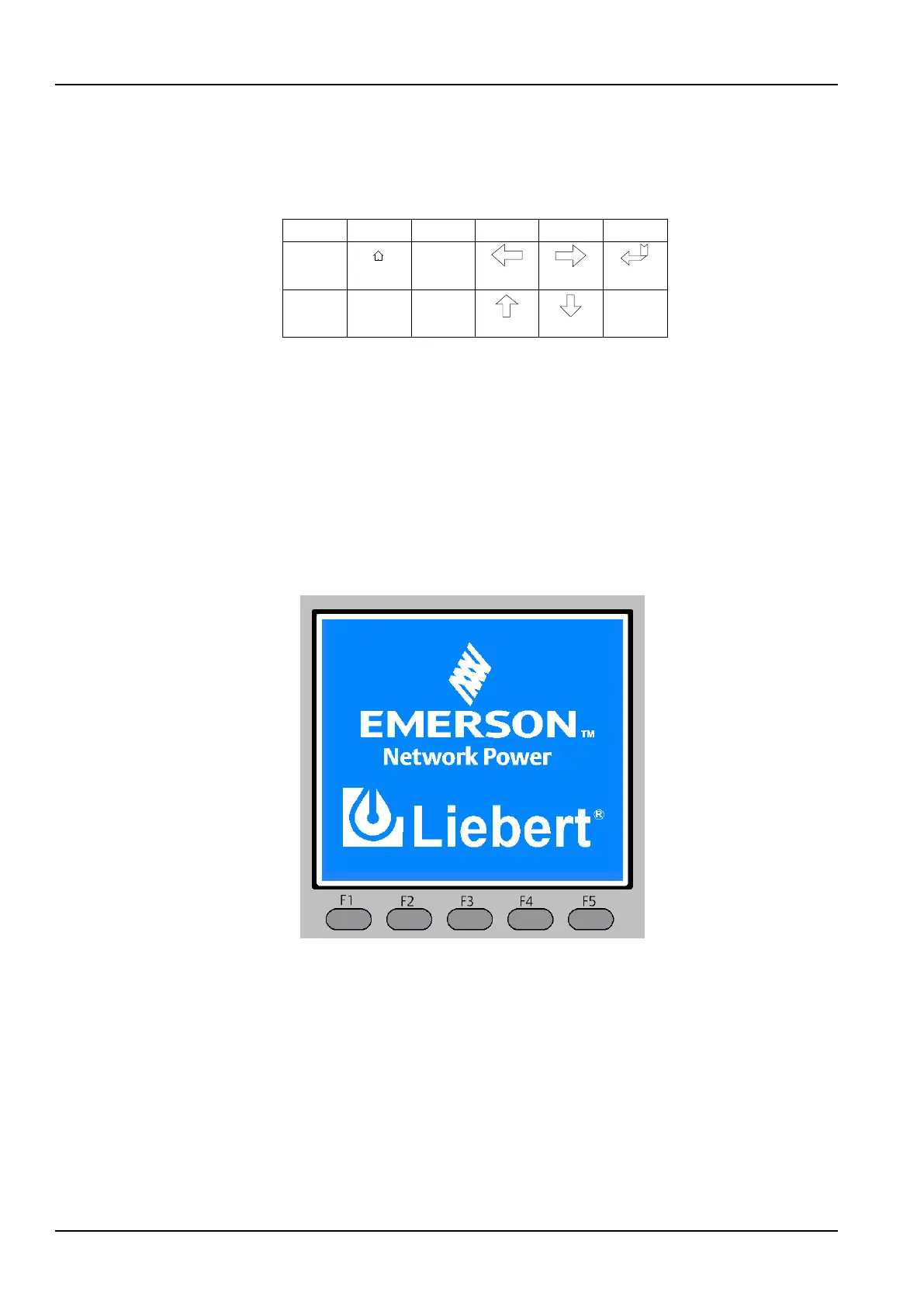
The operator control and display panel provides an LCD and five menu keys (F1, F2, F3, F4, and F5). The menu
keys are described in Table 4-5.
Table 4-5 Description of menu keys
Function 1
Function 2
F1 F2 F3 F4
ESC
Escape
Left
Up
Right
Down
Enter
Key F5
HOME
Function 1
Key F1 F2 F3 F4 F5
Function 2
HOME Escape Left Right Enter
UP
Down
ESC
Providing 320 × 240 dot matrix graphic display, the user-friendly and menu-driven LCD allows you to easily
browse through the input, output, load and battery parameters of the UPS, learn current UPS status and alarm
information, perform functional setting and control operation. The LCD also stores up to 1024 historical
records that can retrieve for reference and diagnosis.
4.2 LCD Screen Types
4.2.1 Start Screen
Upon UPS start, the UPS executes self-test, and the start screen appears and remains approximately 15
seconds, as shown in Figure 4-2.
Figure 4-2 Start screen
4.2.2 Primary Screen
After the UPS starts and finishes self-test, the primary screen appears, as shown in Figure 4-3. The primary
screen is divided into four windows: system information window, menu window, data window and keypad
window.



 To Next Page