64 Chapter 8 Options
APM 300 Integrated UPS Single Module And Parallel System User Manual
1. Remove the cover of Intellislot port. Note to reserve the removed screws and take care of the cover for
future use.
2. Insert the SIC card (along two sides of the Intellislot port) into the port position recommended in Table 8-1,
and then fasten the screws.
For more information of the SIC card, refer to Site Interface Web/SNMP Agent Card User Manual in accessory.
8.2.5 Relay Card
The UPS provides relay card for the user to use dry contact signals to monitor the UPS. It is hot pluggable for
easy installation.
The relay card can provide four channels of relay digital signal output to the remote site. They are UPS on
Battery, Battery Low, UPS on Bypass or in Standby, UPS Faulty. Each dry contact signal output channel provides
both normally open and normally closed ports. The relay card can also receive three channels of digital signal
input, two of which control the UPS turn-on and turn-off respectively, the third is reserved.
Appearance and hardware description
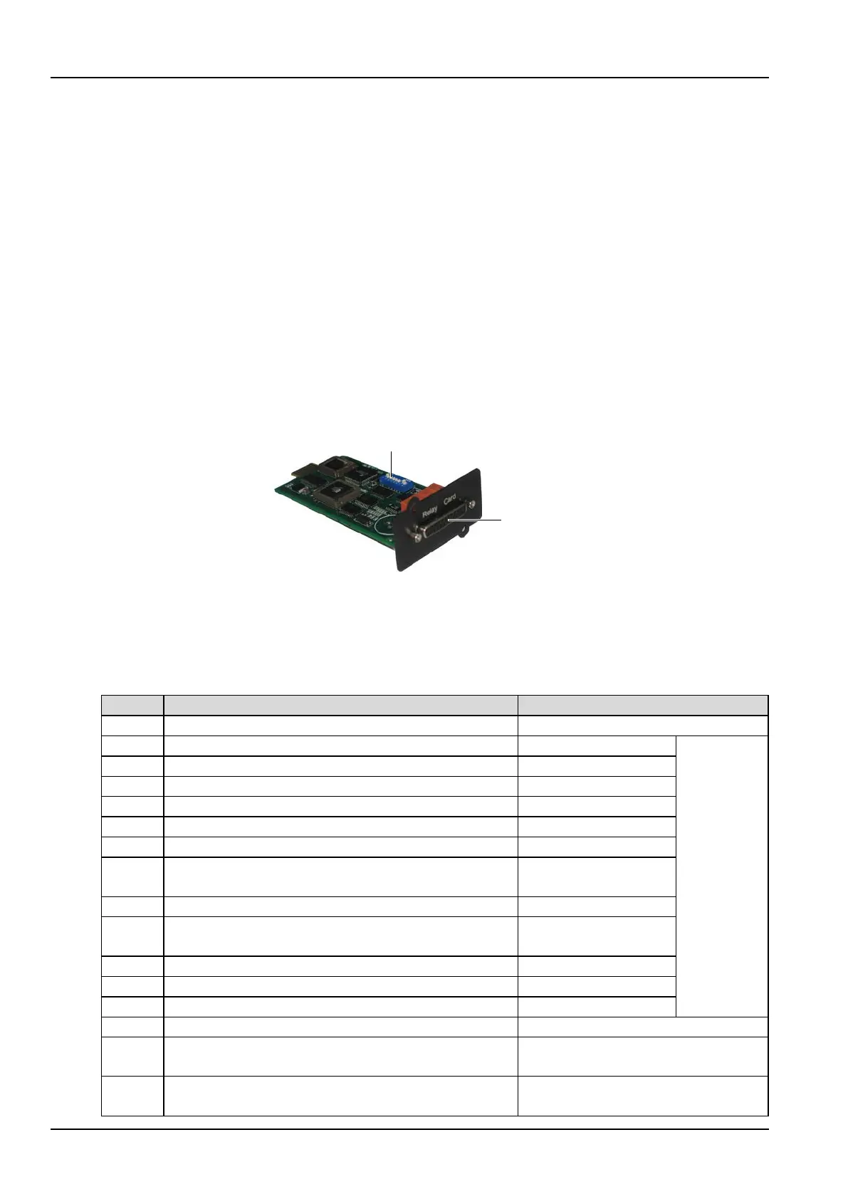
The appearance of the relay card is shown in Figure 8-4.
Figure 8-4 Relay card appearance
The DIP switch is used to configure the UPS turn-on and turn-off signal input function of the relay card. The
DB25 connector provides dry contact signal input and output. The pins of the DB25 connector are described
in Table 8-2.
Table 8-2 DB25 connector pin description
9
~
15Vdc (reserved for factory use)
K0_NO, Channel 0 dry contact normally open output contact
Electrical
parameter:
30Vdc/1.8A,
resistive load
K0_COM, Channel 0 dry contact common output contact
K0_NC, Channel 0 dry contact normally closed output contact
K1_NO, Channel 1 dry contact normally open output contact
K1_COM, Channel 1 dry contact common output contact
K1_NC, Channel 1 dry contact normally closed output contact
Pin 17 K2_NO, Channel 2 dry contact normally open output contact
in Standby
K2_COM, Channel 2 dry contact common output contact
Pin 18
K2_NC, Channel 2 dry contact normally closed output contact
Open: UPS on Bypass or in
Standby
K3_NO, Channel 3 dry contact normally open output contact
K3_COM, Channel 3 dry contact common output contact
K3_NC, Channel 3 dry contact normally closed output contact
DRY_IN2, Channel 2 dry contact signal input
Pin 12 DRY_IN1, Channel 1 dry contact signal input
The UPS is turned off if this contact is
closed for more than one second
Pin 25 DRY_IN0, Channel 0 dry contact signal input
The UPS is turned on if this contact is
closed for more than one second



 To Next Page