Mechanical Installation
Vertiv | Liebert CRD10 | User Manual 42
according to site condition.
Table 3-8 Equivalent Length of Partial Components
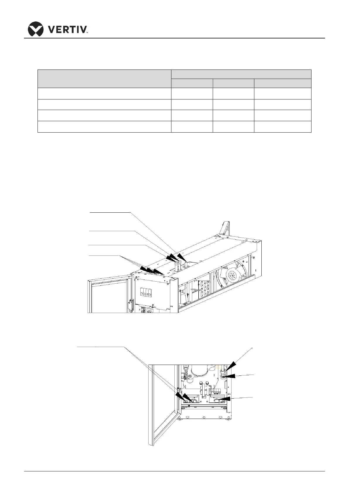
As shown in Figure 3-17 and 3-18, the unit has refrigerated pipe connectors and labels on top and bottom.
Don’t burn the labels during brazing. These labels assist and point out the connections to the discharge pipe
and liquid pipe of the indoor unit. The horizontal sections of the discharge pipes must be tilted downwards
from the compressor with a slope of at least 1:200 (5mm down for every 1m run). The discharge pipes must
be insulated from heat at the location where they are routed in the conditioned space (including the raised
floor).
Figure 3-17 Top Pipe Connectors
Figure 3-18 Bottom Pipe Connectors