LIEBERT® GXT5™ UPS
6000VA HV, 208V (L1, L2, G) IN, 208V OUT
GXT5-6KL630RT5UXLN
Quick Installation Guide
SL-70306_REV1_11-19 1
I M P O RTANT: Before installing,
connecting to supply or operating
your Liebert GXT5 UPS, please
review the Safety and Regulatory
Statements sheet. For detailed
installation, operating, maintenance
and troubleshooting info
rmation refer to the GXT5 User
Guide for your model available at
www.Vertiv.com.
INSTALLATION
1. Inspecting the UPS
Inspect the UPS for any signs of
obvious damage. If damage is
visible, do not proceed and call
our warranty support line for
assistance at 1-800-222-5877
menu option 3, or email at
microups.warranty@vertiv.com.
2. Choosing a location
Install the UPS in a
temperature-controlled
environment that is free of
corrosive and conductive
contaminants. Avoid locations
near heat or water sources and
exposed to direct sunlight.
For proper ventilation, leave
four inches clearance on all
sides of the UPS.
The input outlet should be
nearby and easily accessible.
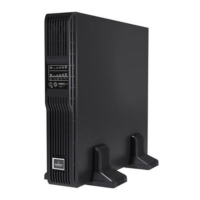
3. Installing the UPS
The UPS and optional External
Battery Cabinets may be
installed in either a tower or rack
conguration. For tower
installation, assemble and attach
the tower support stands. For
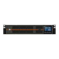
rack installation, attach the
brackets to the UPS, install the
rail kit in the rack if needed, and
install the UPS in the rack.
NOTE:
This UPS is not for use in a
computer room as dened in the
standard for the protection of
electronic computer/data
processing equipment of ANSI/
NFPA 75.
Rear Panel of GXT5-6KL630RT5UXLN
GXT5 UPS
# Description
1 Liebert® IntelliSlot™ port
2 Terminal-block/Dry-contact communication connectors
3 RS-485 port
4 USB port
5 RS -232 port
6 REPO connector
7 L6-30R output breaker
8 External-battery-cabinet connector
9 Programmable outlet maintenance bypass breaker
10 Programmable outlet maintenance bypass breaker
11 Maintenance-bypass breaker
12 Input circuit breaker
13 L6-30P input plug
14 L6-30R output receptacle (2x)
15 Programmable L6-20R output breaker
16 Programmable L6-20R output breaker
17 Programmable L6-20R output receptacle (2x)