Vertiv I Liebert Air Cooled Condenser I User Manual 13
Chapter 3 Application of Fan Speed Controller
This chapter introduces the use of the fan speed controller, which includes the definitions of
wiring terminals, introduction of human-machine interface (HMI) and operation of HMI. This
chapter is mainly provided for the factory maintenance personnel. It is recommended that
users should not operate the fan speed controller unless necessary.
The configured fan number must be the same as the number of the actual fans, or
else a false alarm will be generated. Refer to Configuration data main menu
interface in 3.3.2 Main Menu Interface for detailed settings.
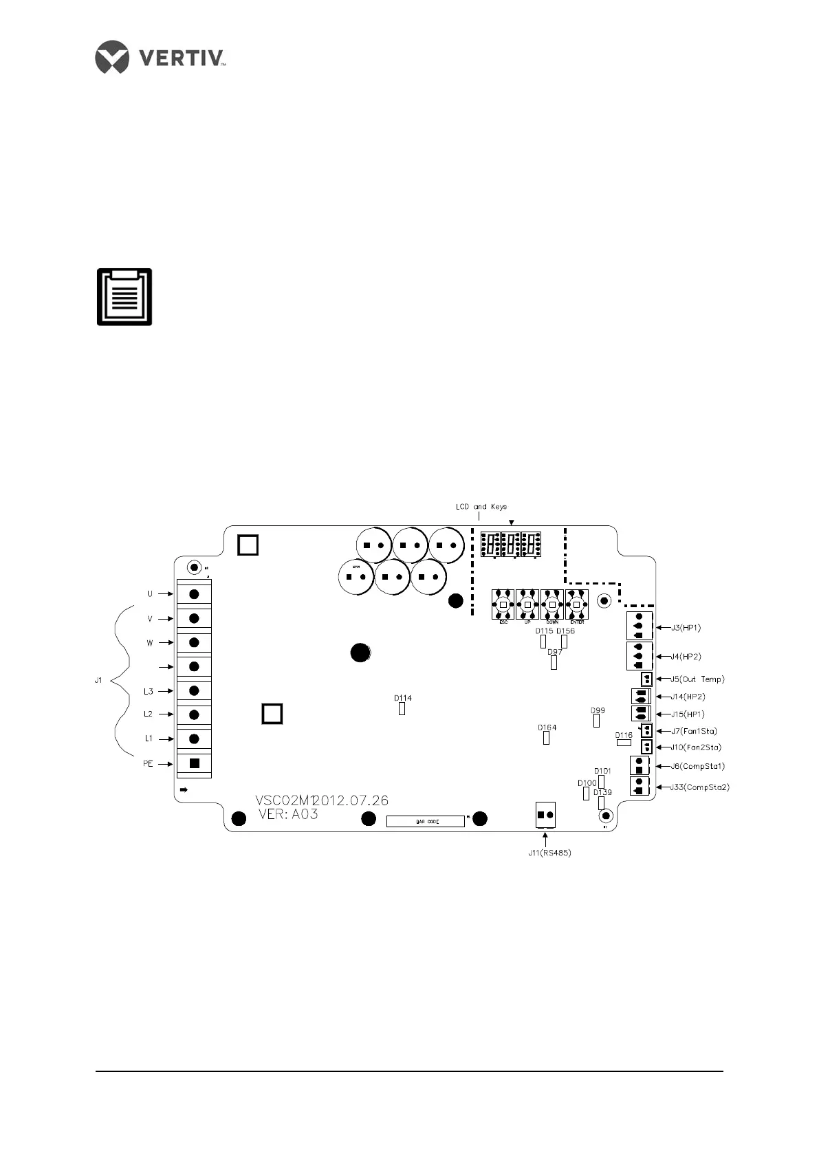
3.1 Wiring Terminals
The wiring terminals are located on the fan speed controller board (Refer Figure 2-5 and
Figure 2-6). Their distribution is shown in Figure 3-1 and the definitions are listed in Table 3-1.
Refer to Circuit Diagram for detailed connections.
Figure 3-1 Layout of wiring terminals