Vertiv I Liebert Air Cooled Condenser I User Manual 15
Indicators
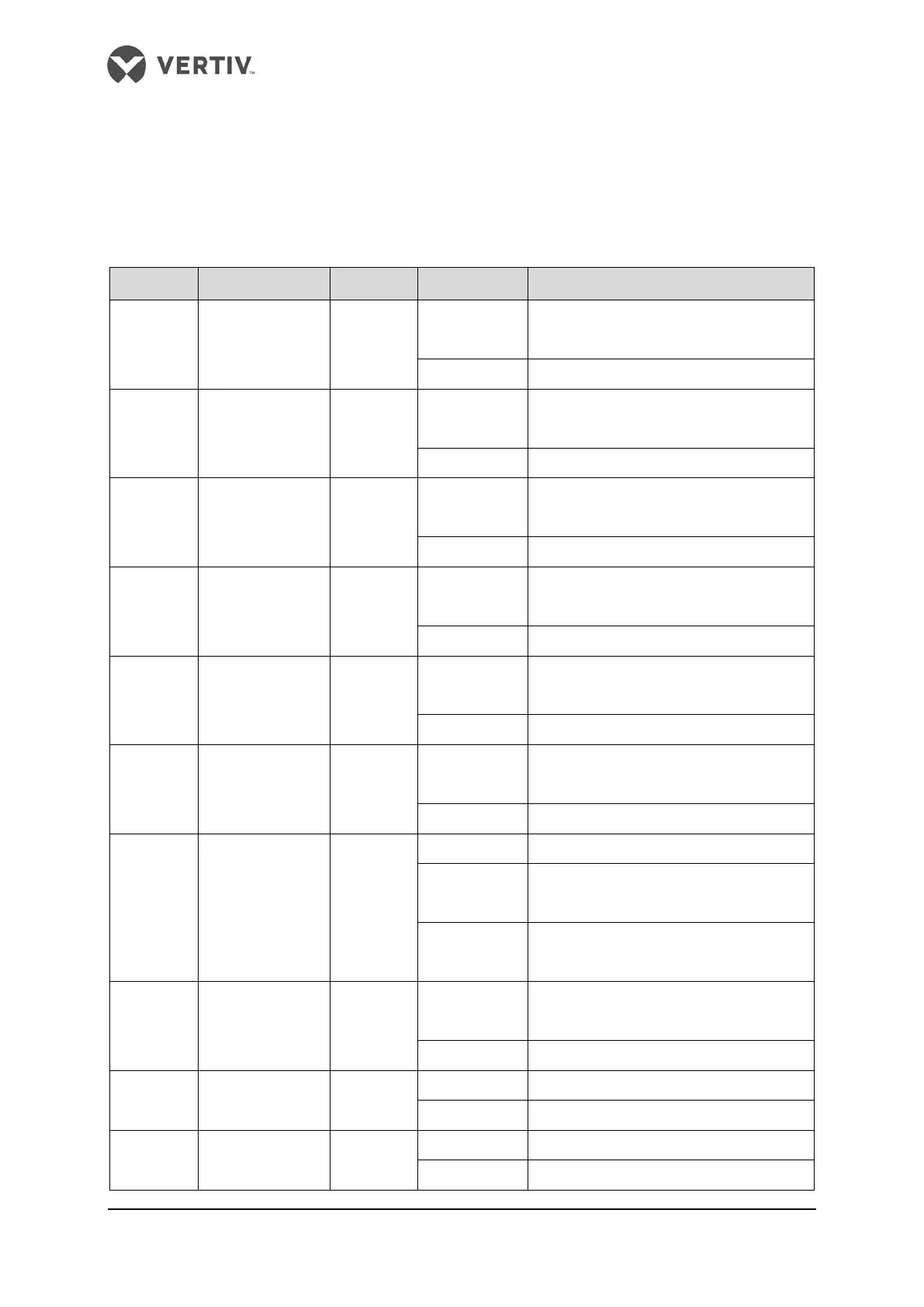
There are ten indicators (Refer Figure 3-1) on the fan speed controller board. Refer Table 3-2
for the functions of indicators.
Table 3-2 Functions of indicators
Silk print Definition Color State Function
D97
+5V Power
indicator
Yellow
On
The CPU circuit of fan speed controller
board is supplied with 5V power
Off The fan speed controller board is faulty
D115
+12V Power
indicator
Yellow
On
The fan speed controller board is supplied
with +12V power
The fan speed controller board is faulty
D116
+24V Power
indicator
Yellow
On
The fan speed controller board is supplied
with +24V power
The fan speed controller board is faulty
D139
VCOM Power
indicator
Yellow
On
The fan speed controller board is supplied
with VCOM power
The fan speed controller board is faulty
D156
-5V Power
indicator
Yellow
On
The fan speed controller board is supplied
with -5V power
Off The fan speed controller board is faulty
D114
VCC_BOT Power
indicator
Yellow
On
The fan speed controller board is supplied
with VCC_BOT power
The fan speed controller board is faulty
D99 Run indicator Green
The fan speed controller board is faulty
(slowly)
The fan is not running
(quickly)
The fan is running
D164 Alarm indicator Red
On
Fan speed controller detects an
alarm(alarms)
D100
RS485 sending
indicator
Green
On RS485 is sending data
D101
RS485 receiving
indicator
Green