17
Liebert
®
MC - UM - 10019237MAN_ENG - 31.03.2022
8.6.3 Controlled by indoor Unit
NOTICE
Risk of control malfunction.
Can cause improper unit operation.
Make sure that all low voltage electrical wiring has been performed per the schematic diagram provided and that all
low voltage wiring connections are tight.
Specications
Modbus Liebert
®
MC remote condensers are designed to use Modbus communication between Liebert
®
MC
and Liebert
®
iCOM
TM
control on main unit.
Modbus lenght restirctions
Do not run the Modbus cable in the same conduit, raceway or chase used for high-voltage wiring.
For Modbus network lengths greater than 130m, please contact Vertiv™ Technical Support.
Modbus cable specications:
The Modbus wiring is eld-supplied and must be:
• shielded
• 24-18 AWG (0.5 mm²) stranded tinned copper until 107m, 18-16 AWG (0.75 mm²) stranded tinned
copper until 130m
• twisted pair (minimum 8 twists per foot)
• low capacitance (17pF/ft or less)
• plenum rated (NEC type CMP) if required by local codes
• UV and moisture resistant or run within conduit once in an outdoor environment, and must be
temperature and voltage rated for conditions present.
Examples: Belden part number 89207(plenum rated) or Alpha Wire part number 6454 (UV resistant
outdoor rated) category 5, 5e or higher.
CAUTIONS
Do not run the Modbus cable in the same conduit, raceway or chase used for high-voltage
wiring.
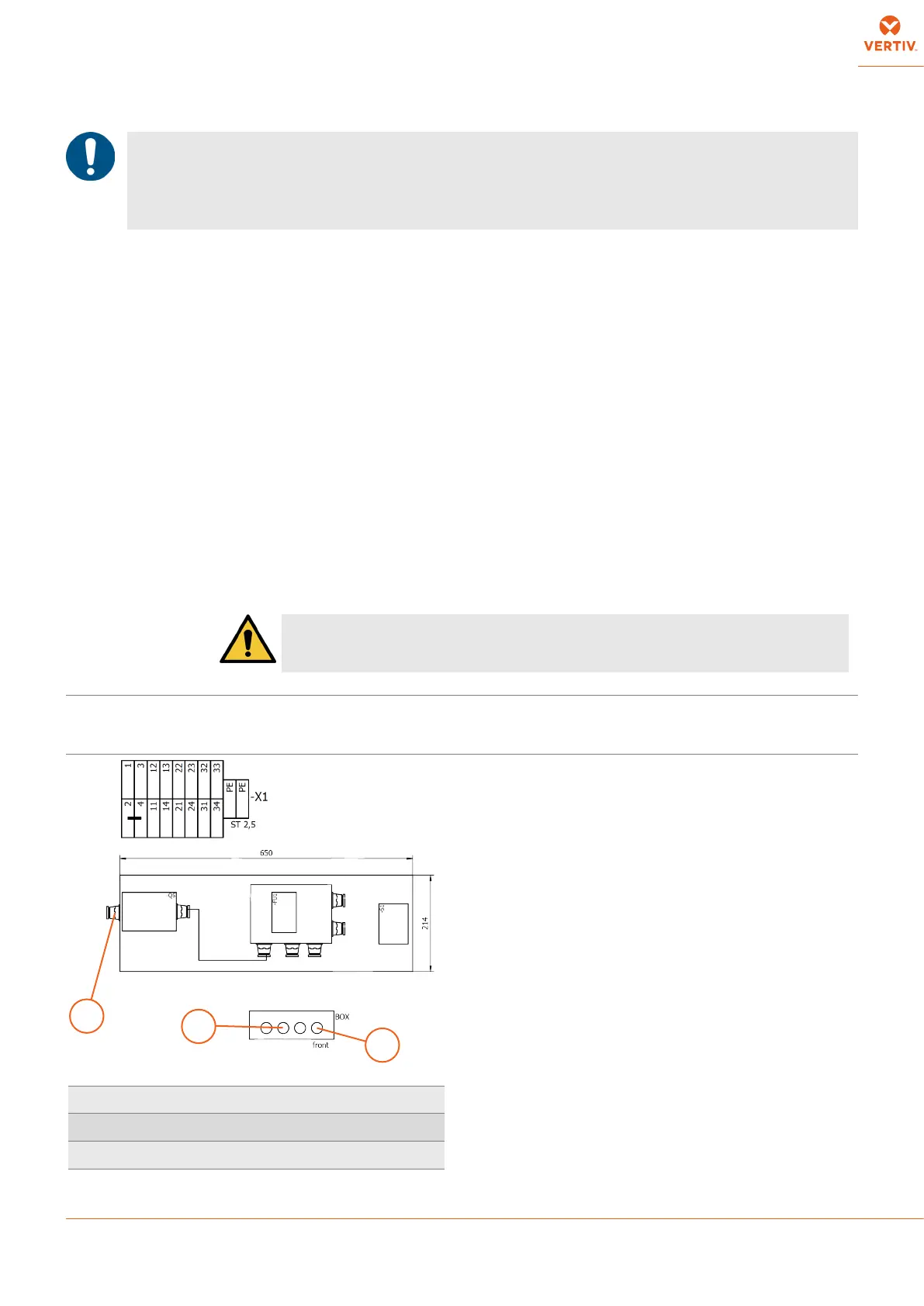
Addressing All the MC condensers are shipped with standard fan addressing: 31, 32 (up to 4 fans). In case of
dual circuit units, it is required to change the addressing of fan of the second circuit in 41, 42, 43, 44,
perspectively.
3
1
2
1 Primary high-voltage entrance M20 cable gland
2 Modbus IN M20 cable gland
3 Modbus OUT M20 cable gland