Vertiv | +24 VDC Power System User Manual (Section 6013) | Rev. G
Manual Battery Disconnect Switch and Indicator (List RB, RC, RD Only)
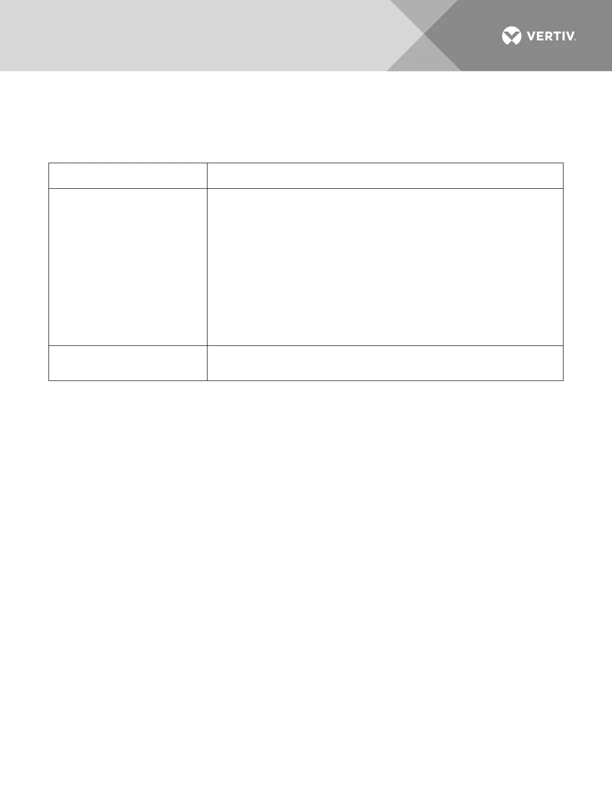
Refer to Table 3.
Table 3:
Manual Battery Disconnect Control and Indicator
(Normal/Disconnect
Switch)
•
(Disconnect Switch
Position)
•
(Normal Switch Position)
This is a locking type toggle switch. To operate switch, pull out switch
handle and move handle left or right to desired position. Release handle to
lock into new position.
• Placing the switch in this position causes the associated contactor to
open, thus disconnecting battery from the power system and loads.
• Returning the switch to this position reconnects battery to the power
system and loads.
(Battery Disconnect Indicator)
Illuminates red if the NORM/DISC battery disconnect switch is placed in the
DISC position.