Vertiv | NetSure 7100 Series Quick Start Guide (QS582127000) | Rev. T
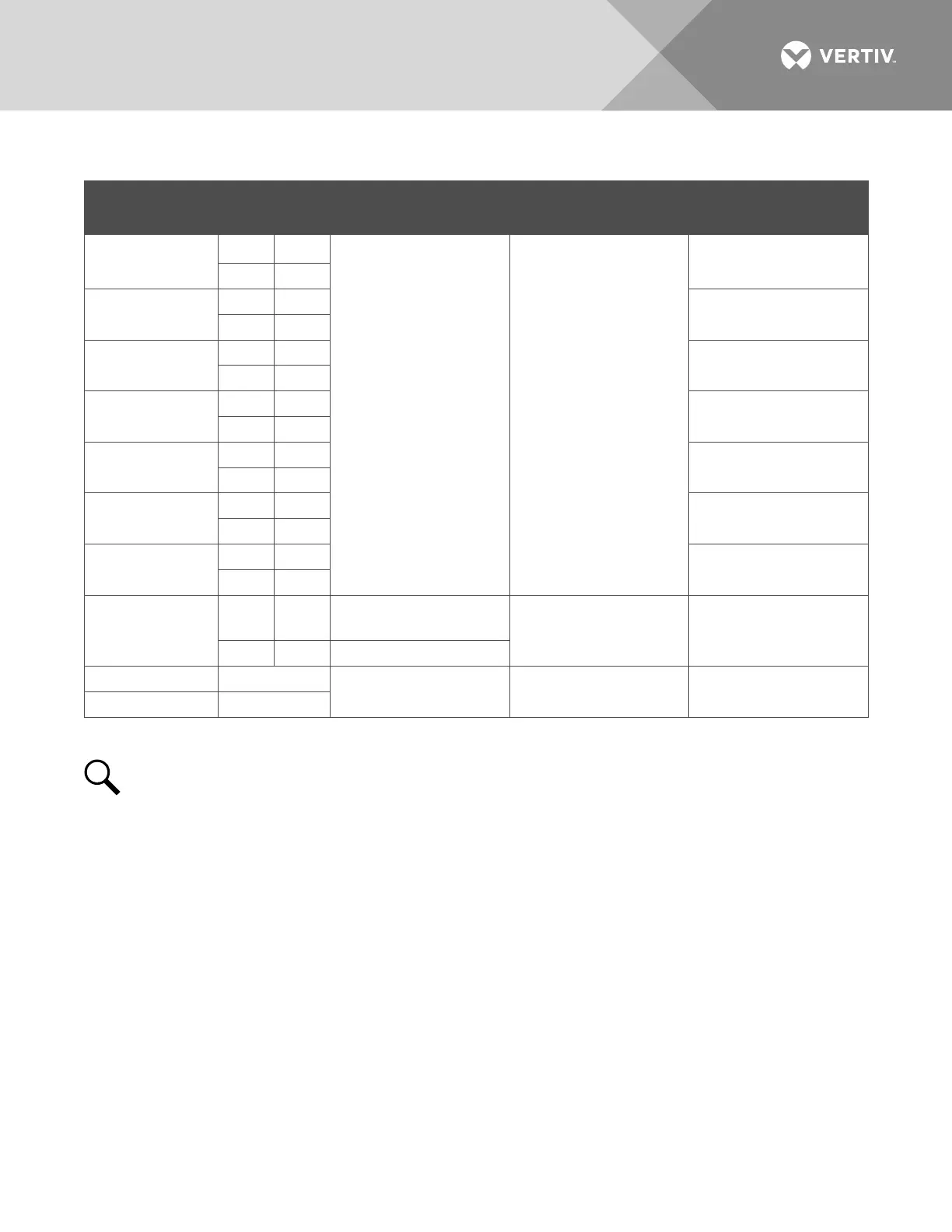
Table 1:
Programmable Digital Inputs – IB2 Board
Programmable
Digital Input
IB2
Pin No.
Factory
Wiring
Default Digital
Input Function
Customer Defined
Digital Input Function
1
J3-2 +
The digital inputs may
be preprogrammed for
specific functions and
have factory wiring
connected. Refer to the
configuration drawing
(C-drawing) supplied
with your system for
your system’s specific
configuration.
The digital inputs may
be preprogrammed for
specific functions.
Refer to the
configuration drawing
(C-drawing) supplied
with your system for
your system’s specific
configuration.
J3-1 –
2
J3-4 +
J3-3 –
3
J3-6 +
J3-5 –
4
J4-2 +
J4-1 –
5
J4-4 +
J4-3 –
6
J4-6 +
J4-5 –
7
J5-2 +
J5-1 –
8
J5-4 +
(to customer
ESTOP switch)
ESTOP
J5-3 – -48 VDC
-- J5-5
not used not used not used
-- J5-6
NOTE!
-48V is factory wired to the Digital Input #8 (-) terminal for your convenience and function
predefined for ESTOP. Customer-furnished system ground applied to terminal Digital Input #8 (+)
activates the ESTOP function. The ESTOP function shuts down and locks out the rectifiers or 400V DC
input converters, opens the LVD’s, and shuts down the optional -48V to +24V DC converters. When the
ESTOP signal is removed, LVD’s close (if battery present) and -48V to +24V DC converters restart. To
restart the rectifiers or 400V DC input converters; turn input power to the rectifiers/converters OFF, wait
30 seconds or more (until the LEDs on the module extinguish), then turn input power to the
rectifiers/converters ON.

 Loading...


