Contents
1. Overview.........................................................................................................................2
2. Product Description.......................................................................................................3
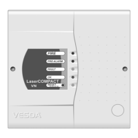
2.1 Front View of LaserCOMPACT........................................................................................3
2.2 Product Model, Approvals and Standards Label.............................................................. 3
2.3 Operation .........................................................................................................................4
2.3.1 LED and Reset/Isolate Push Button Switch Functions ............................................4
2.4 Factory Default Settings...................................................................................................5
2.4.1 Factory Default User Levels.....................................................................................5
2.4.2 Factory Default PIN Numbers .................................................................................. 5
2.5 LaserCOMPACT Detector Models...................................................................................5
2.5.1 Relays Only (RO) Model (Part No. VLC 500)...........................................................5
2.5.2 VESDAnet (VN) Model (Part No. VLC 505) ............................................................5
2.6 Detector Mounting............................................................................................................6
2.7 Relay Outputs .................................................................................................................. 6
2.8 Auxiliary Terminals...........................................................................................................7
2.9 Cable Entry Ports.............................................................................................................7
2.10 Event Log......................................................................................................................... 7
3. Assembly Description ...................................................................................................8
3.1 Assembly Description.......................................................................................................8
3.2 Front Cover and LEDs ...................................................................................................10
3.3 Termination Card ...........................................................................................................10
3.4 Cable Entry Ports...........................................................................................................10
3.5 Air Inlet Port ...................................................................................................................10
3.6 Air Filter Cartridge..........................................................................................................10
3.7 Aspirator.........................................................................................................................11
3.8 Air Exhaust Port .............................................................................................................11
3.9 Laser Detection Chamber..............................................................................................11
3.10 Processor Card..............................................................................................................11
4. Termination Card Details ............................................................................................12
4.1 Wire Terminal Location for RO Model ...........................................................................12
4.2 Wire Terminal Location for VN Model............................................................................12
4.3 Power Terminals ............................................................................................................13
4.4 VESDAnet Terminals (VN Model only) ..........................................................................13
4.5 Relay Terminals .............................................................................................................14
4.6 Programming Socket .....................................................................................................15
4.7 Auxiliary Terminals.........................................................................................................15
4.7.1 Bias Terminals .......................................................................................................15
4.7.2 Reset Terminals (General Purpose Input) .............................................................16
4.7.3 Remote LED Terminals..........................................................................................16
5. Specifications...............................................................................................................17
6. Factory Default Settings.............................................................................................. 18
7. Alarm Threshold Settings ...........................................................................................19
8. Physical Dimensions...................................................................................................20
9. Parts Replacement....................................................................................................... 22
9.1 Opening the Detector.....................................................................................................23
9.2 Closing the Detector.......................................................................................................23
9.3 Replacing the Air Filter Cartridge...................................................................................23
9.4 Replacing the Aspirator.................................................................................................. 24