LaserCOMPACT Product Manual VESDA
®
6 Version 1.0
2.6 Detector Mounting
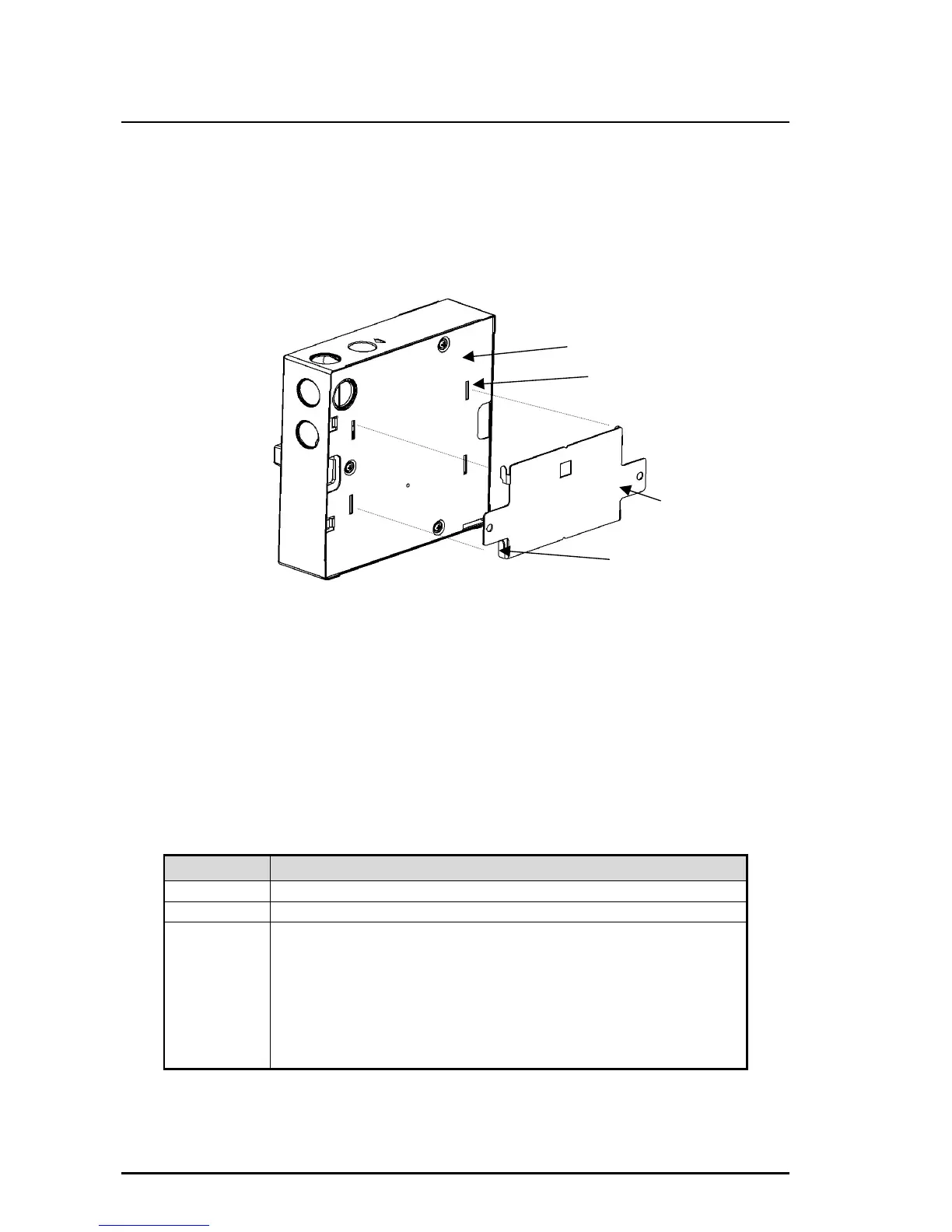
The LaserCOMPACT comes with a separate metal mounting bracket that is attached onto the
mounting location. The detector can only be mounted with the supplied mounting bracket. The
back of the detector is slotted over the four tabs on the mounting bracket and is locked in place
with an anti-tamper screw located inside the enclosure. Refer to Figure 3 for mounting and
Figure 6 for the anti tamper screw location.
Figure 3 Mounting the Detector onto the Mounting Bracket
2.7 Relay Outputs
There are three relays (Fire, Pre-Alarm and Fault) for interfacing to external devices or to the
Fire Alarm Panel. The relays are programmable to the energised (latched) or de-energised (non-
latched) states via a PC or LCD Programmer. Refer to the table below for the conditions for
these relays to change states.
Note: The Fault relay is set to the energised (latched) state on power up and is de-energised
(unlatched) when a fault or Alert condition is present. Connection is made between the
NO and C terminals when the relay is energised.
RELAY CONDITIONS FOR RELAYS TO CHANGE STATES
Fire Fire alarm smoke threshold level is initiated. (Relay is energised)
Pre-Alarm Pre-Alarm smoke threshold level is initiated. (Relay is energised)
Fault Fault found on detector or on VESDAnet loop.
Air flow Normalisation is initiated.
System Isolation is initiated.
(Relay is de-energised for all three conditions above)
When the Overlay Alert function has been selected and when the
Alert smoke threshold level has been initiated or when a fault is
present. (Relay is de-energised)
Note: The above relay states are not applicable when the relay states are reprogrammed by the
user.
Back of the box
Mounting bracket
Bracket tab X 4
Rectangular Slots X 4
 Loading...