12
5. Visually inspect socket contact array
1. First Pass Inspection
i. Scan socket contact array at varying angles noting the presence of any foreign material
ii. If foreign material can’t be blown off by compressed air, or mechanical damage (Mode1 or 4)
observed, reject the motherboard for further evaluation or socket replacement.
2. Second Pass Inspection
i. Repeat 2 more times to sight down the rows and columns from each of the 4 sides of the socket to
ensure all contacts within the array are inspected
ii. Inspect for Mode2, Mode3, and Mode5 failures
Note: Refer to the Test Module for detail visual inspections
6. Assemble LGA775 socket PnP cap
i. Secure/Hook the back side of PnP cap.
ii. Snap down the front side to fully secure
7. Close the Socket
Intel Reference Thermal Solution Assembly
NOTE: Depending on the configuration, Thermal Solution Integration procedure could perform with
M/B alone or with M/B in the Chassis.
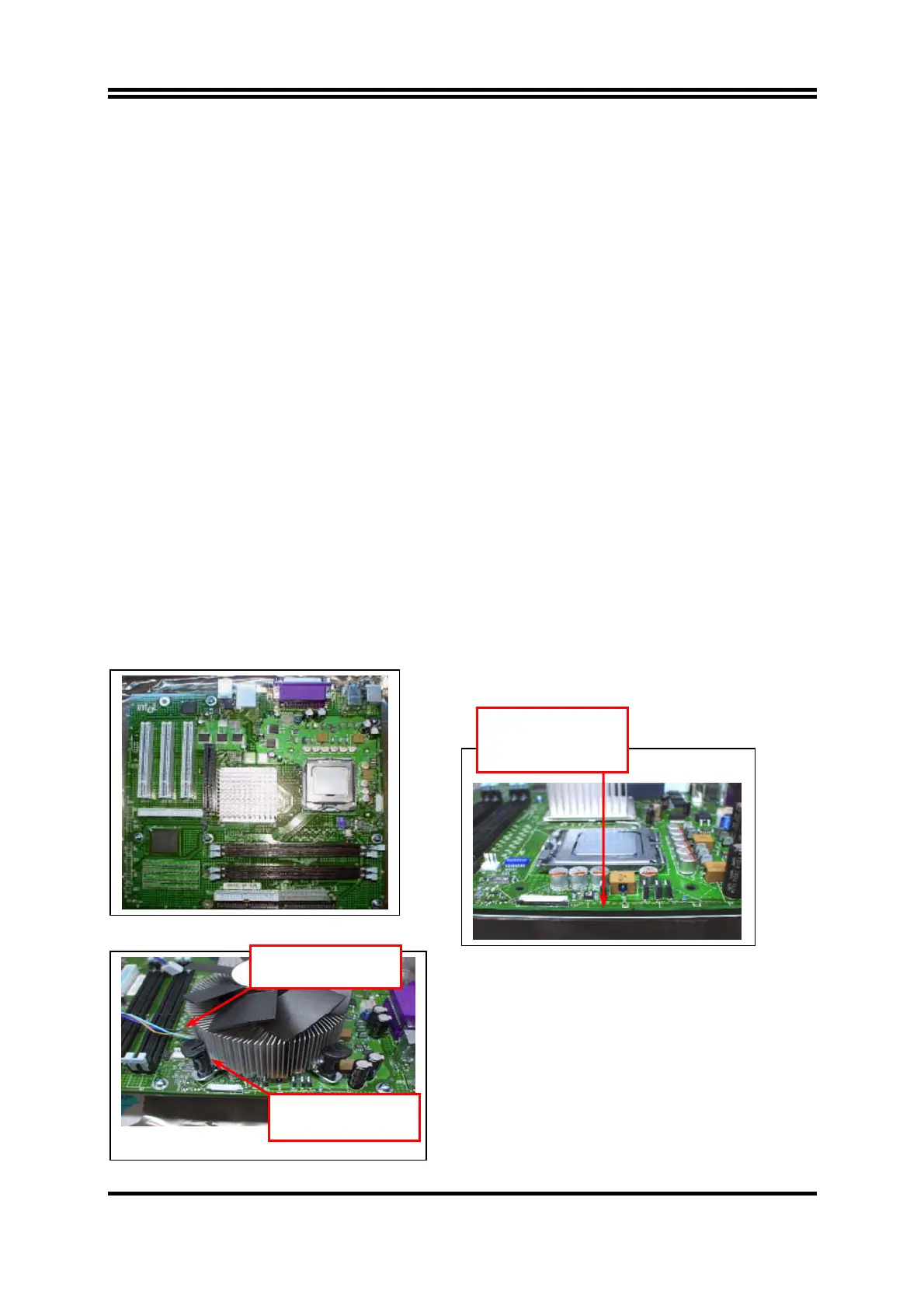
1. Place motherboard on support structure providing
minimum 0.150-inch backside clearance
2. Apply 300 mg of Thermal Interface Material (Shin-
Etsu G751) onto center of IHS
0.150-inch backside
clearance for fastener
installation
Fan cabled on side
closest to MB heade
Fastener slots
pointing straight out
 Loading...