18
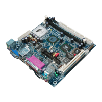
Note: The black pin and white prong will only “snap” on in one orientation
-Check to ensure the black pin is rotated properly for installation with the slot perpendicular to the
heatsink
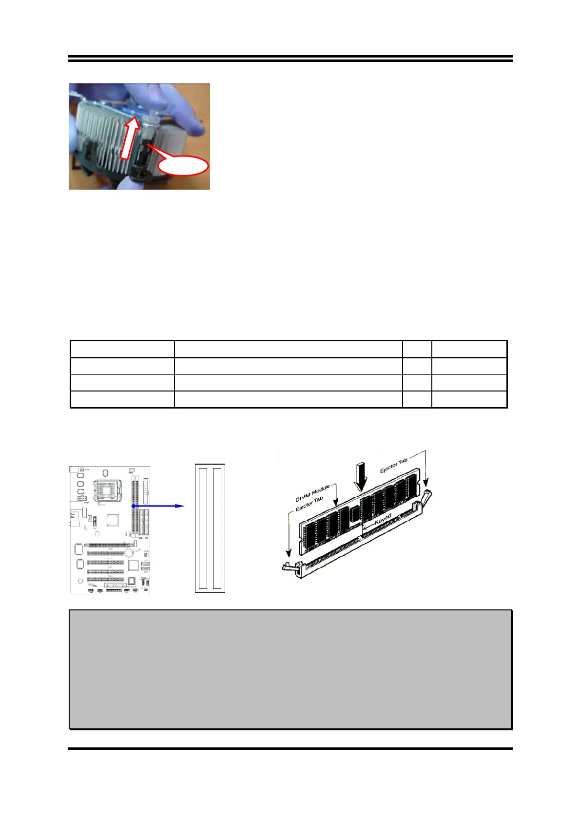
2-4 Install Memory
This motherboard provides two 240-pin DDR2 DUAL INLINE MEMORY MODULES
(DIMM) sides for DDR memory expansion available from minimum memory size of 64MB
to maximum memory size of 2.0GB DDR SDRAM.
Valid Memory Configurations
Bank 240-pin DDR2 DIMM PCS Total Memory
Bank 0, 1 (DDR1) DDRII533/DDRII400 DDR DRAM Module X1 64MB∼1.0GB
Bank 2, 3 (DDR2) DDRII533/DDRII400 DDR DRAM Module X1 64MB∼1.0GB
Total System Memory (Max. 2.0GB) X2 64MB∼2.0GB
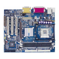
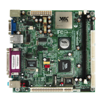
Generally, installing DDR2 SDRAM modules to your motherboard is very easy, you can refer
to figure 2-4 to see what a 240-pin DDR2 SDRAM module looks like.
DIMM2 (BANK2+ BANK3)
DIMM1 (BANK0+ BANK1)
NOTE!
When you install DIMM module fully into the DIMM socket the eject tab should
be locked into the DIMM module very firmly and fit into its indention on both
sides.
WARNING!
For the DDR SDRAM CLOCK is set at 133MHz, use only DDR2 533-compliant DDR
Modules. When this motherboard operate at 133Mhz, most system will not even
boot if non-compliant modules are used because of the strict timing issues, if your
DDR Modules are not DDR2 533-compliant, set the SDRAM clock to 133MHz to
ensure system stability.
Figure 2-4
Click