I-768N / Series 768N FireLock NXT
™
Dry Valve / Installation, Maintenance, and Testing Manual
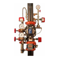
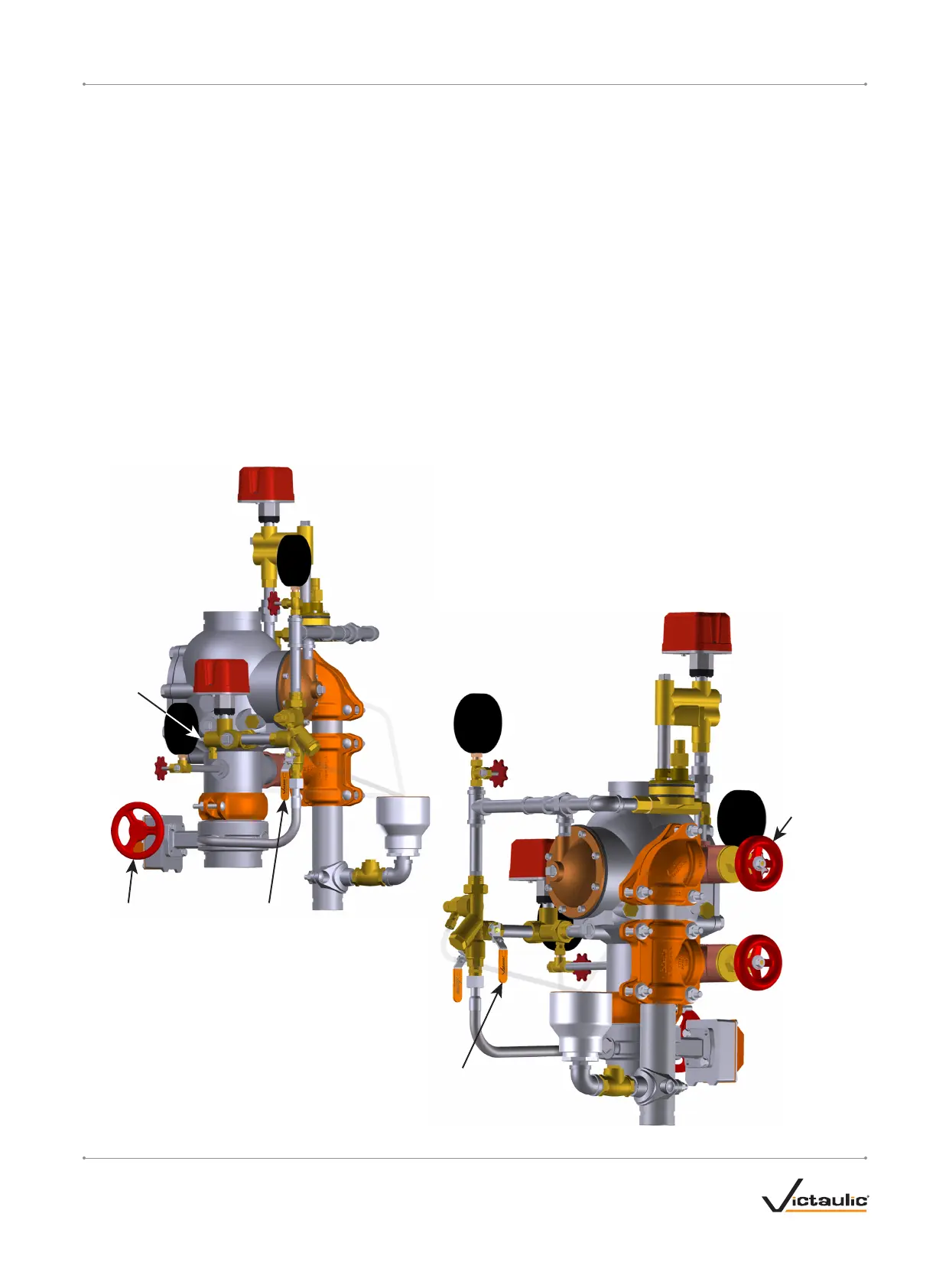
Charge Line
Ball Valve
(Step 1)
Ball Drip
Plunger
(Step 3a)
Water Supply
Main Control
Valve
(Step 2)
Drain Valve
(Steps 3 & 4)
Alarm Test
Ball Valve
(Step 7)
RESETTING THE SYSTEM
Step 1:
Isolate the charge line ball valve by placing it in the closed position.
Step 2:
Close the water supply main control valve.
Step 2a: Isolate the air supply to the system.
Step 3:
Open the system main drain valve. Confirm that the system is drained.
Step 3a: Push in the ball drip plunger to release pressure.
Step 4:
Close the system main drain valve.
Step 5:
Confirm that all system drains are shut and that the system is free
from leaks.
Step 6:
Confirm that the system has been depressurized. The gauges should
indicate zero pressure.
Step 6a: If a Series 746-LPA Dry Accelerator is installed, confirm
that the isolation ball valve is closed.
Step 6b: If a Series 746-LPA Dry Accelerator is installed, open
the ¼-turn vent ball valve.
Step 7:
Confirm that the alarm test ball valve is closed.
Step 8:
Follow steps 4 - 15 of the “Initial System Setup” section.
I-768N_15REV_C

 Loading...