I-768N / Series 768N FireLock NXT
™
Dry Valve / Installation, Maintenance, and Testing Manual
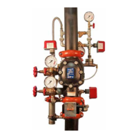
9. Install the clapper seal into the clapper carefully. Ensure that the
seal ring snaps into the clapper completely.
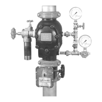
10. Place the seal-retaining ring onto the seal washer of the clapper
seal. Install the seal assembly bolt/bolt seal through the seal-
retaining ring and clapper.
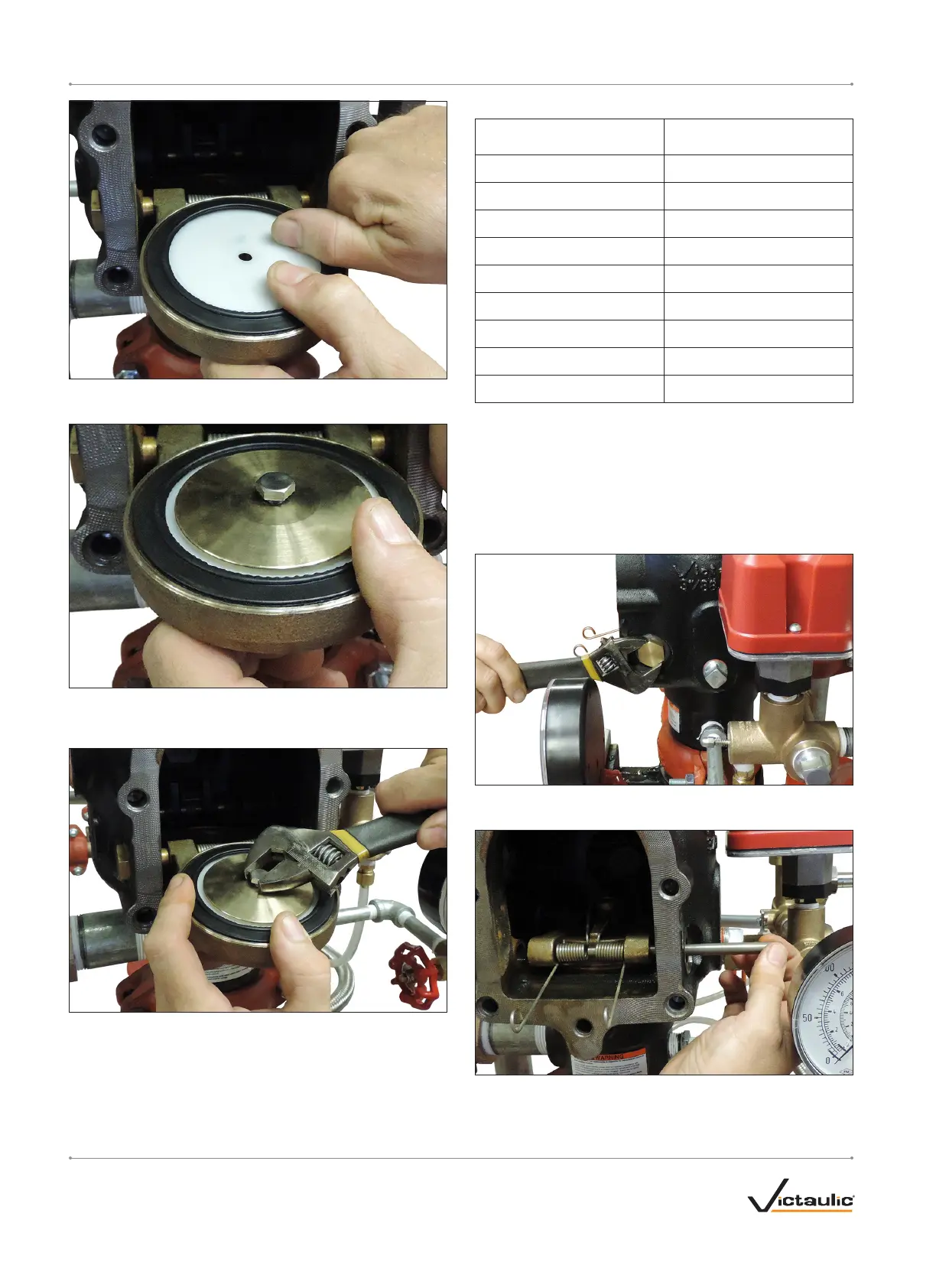
11. Tighten the seal assembly bolt/bolt seal to the torque value listed
in the table on this page to ensure a proper seal.
REQUIRED SEAL ASSEMBLY BOLT/BOLT SEAL TORQUES
Nominal Size
inches or mm
Required Torque
inch-lbs/N•m
1 ½
40
5
2
40
5
2 ½
90
10
76.1 mm
90
10
3
90
10
4
110
12
165.1 m m
160
18
6
160
18
8
160
18
12. Replace the cover plate by following the “Installing the Cover Plate
Gasket and Cover Plate” section.
13. Place the system back in service by following the “Resetting the
System” section.
REMOVING AND REPLACING THE CLAPPER
ASSEMBLY
1. Perform steps 1 – 13 of the “Required Internal Inspection” section.
2. Remove the clapper shaft bushings with o-rings from the valve
body.
3. Remove the clapper shaft. NOTE: As the shaft is being removed,
the clapper spring will drop out of position. Save the clapper spring
for re-installation.
I-768N_ 28 REV_C

 Loading...