I-768N / Series 768N FireLock NXT
™
Dry Valve / Installation, Maintenance, and Testing Manual
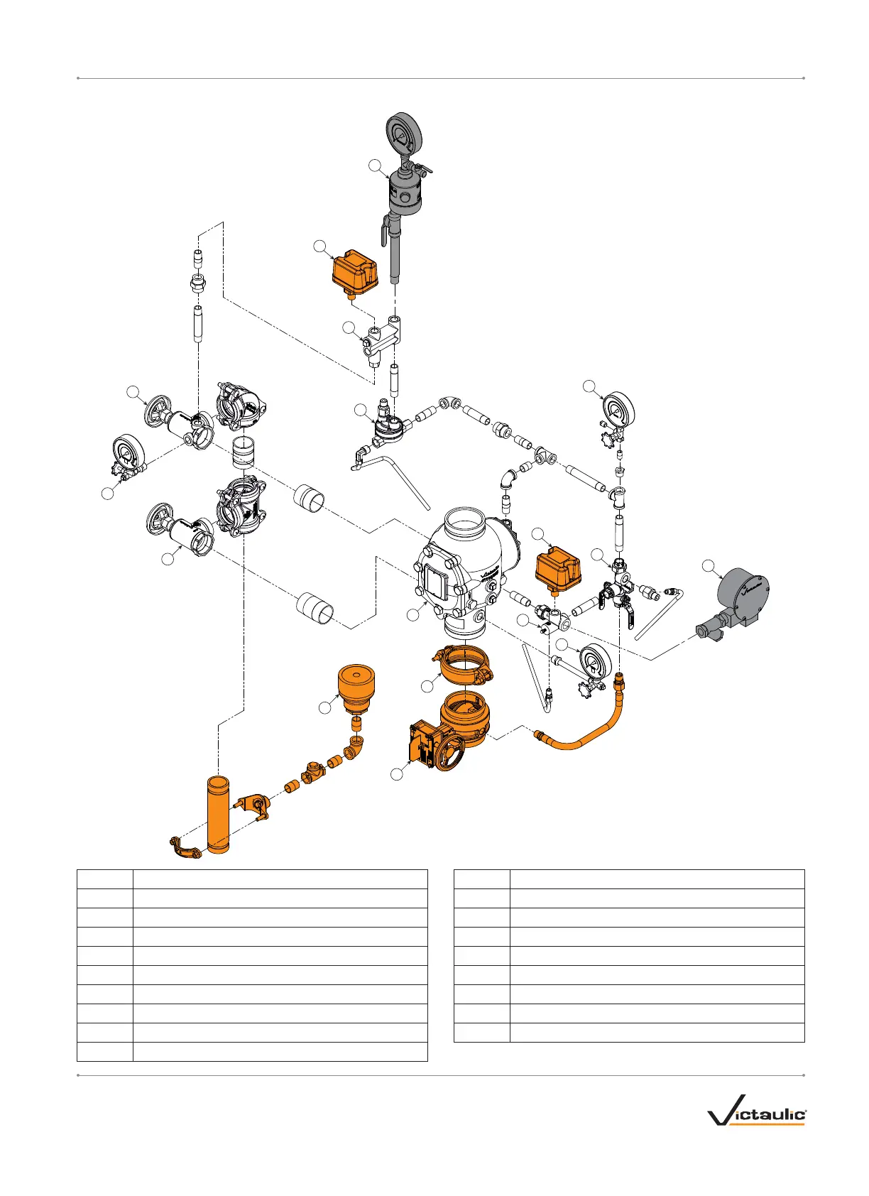
TRIM COMPONENTS – EXPLODED VIEW DRAWING
1
2
3
4
5
6
7
8
9
10
11
12
13
14
15
16
17
Orange shaded areas identify components that are optional equipment.
These components are standard when the VQR assembly is ordered.
Gray shaded areas identify components that are optional equipment.
Item Description
1 Series 768N FireLock NXT Dry Valve
2 FireLock Rigid Coupling
3 Water Supply Main Control Valve
4 Drip Cup
5 Water Supply Main Drain Valve – Flow Test
6 System Pressure Gauge/Gauge Valve Assembly
7 System Main Drain Valve
8 Air Supervisory Pressure Switch
9 Series 746-LPA Dry Accelerator Assembly
Item Description
10 Air Manifold
11 Series 776 Low-Pressure Actuator
12 Charge Line Pressure Gauge/Gauge Valve Assembly
13 Alarm Pressure Switch
14 Priming Manifold Assembly
15 Alarm Manifold Assembly
16 Series 760 Water Motor Alarm Assembly
17 Water Supply Pressure Gauge/Gauge Valve Assembly
I-768N_7REV_C

 Loading...


