I-768N / Series 768N FireLock NXT
™
Dry Valve / Installation, Maintenance, and Testing Manual
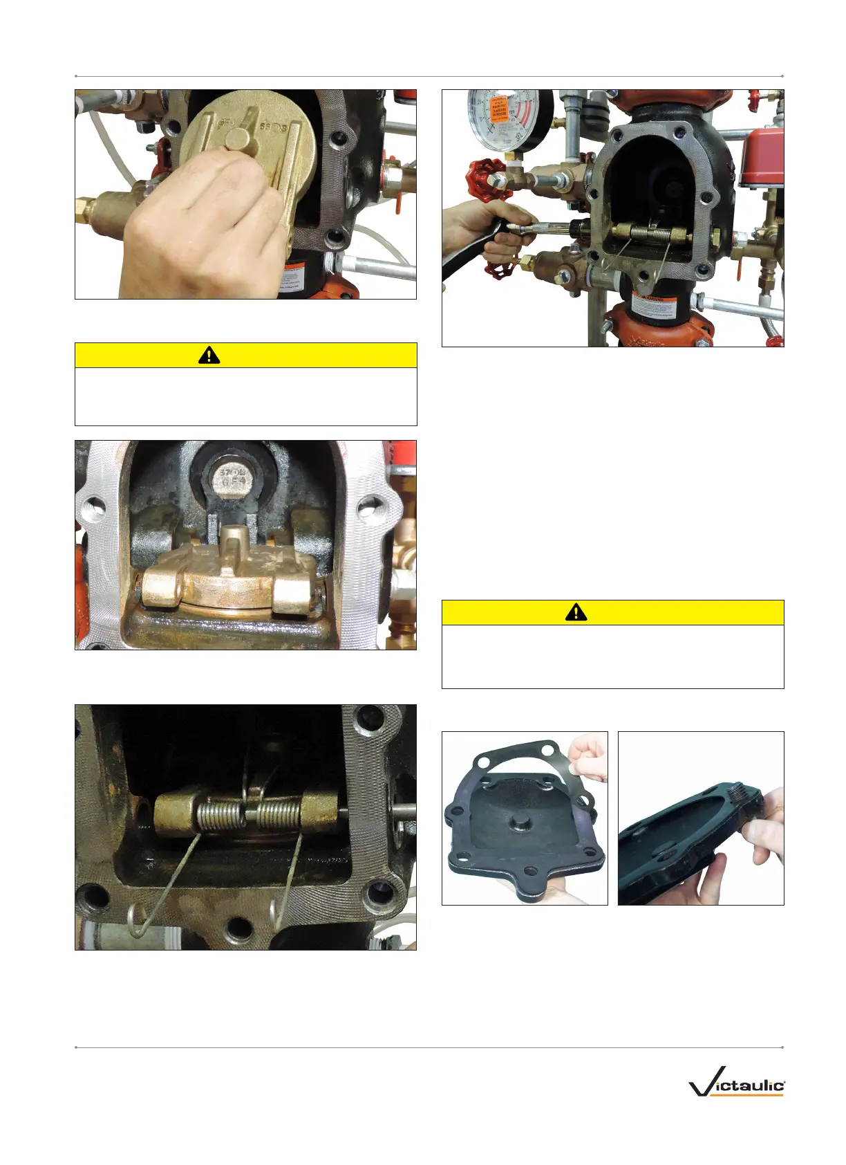
4. Remove the clapper assembly from the valve body seat ring. Clean
the valve body seat ring.
CAUTION
• Use only Victaulic-supplied replacement parts.
Failure to follow this instruction could cause improper valve
operation, resulting in property damage.
5. Place the new clapper assembly onto the valve body seat ring.
Ensure that the holes in the clapper arms align with the holes in
the valve body.
6. Insert the clapper shaft halfway into the valve body.
7. Install the clapper spring onto the clapper shaft. Ensure that the
loop of the clapper spring is facing the clapper, as shown above.
8. Finish inserting the clapper shaft through the clapper arm and
valve body.
9. Ensure that a clapper shaft bushing o-ring is installed on each
clapper shaft bushing.
9a. Apply thread sealant to each clapper shaft bushing. Install the
clapper shaft bushings into the valve body until hand-tight.
9b. Tighten the clapper shaft bushings until metal-to-metal contact
occurs with the valve body. DO NOT exceed 10 ft-lbs/14 N•m of
torque on the clapper shaft bushings.
9c. Check the clapper for freedom of movement.
10. Replace the cover plate by following the “Installing the Cover Plate
Gasket and Cover Plate” section.
11. Place the system back in service by following the “Resetting the
System” section.
INSTALLING THE COVER PLATE GASKET AND
COVER PLATE
CAUTION
• Use only Victaulic-supplied replacement parts.
Failure to follow this instruction could cause improper valve
operation, resulting in property damage.
1. Verify that the cover plate gasket is in good condition. If the gasket
is torn or worn, replace it with a new, Victaulic-supplied gasket.
2. Align the holes of the cover plate gasket with the holes in the cover
plate.
3. Insert one cover plate bolt through the cover plate and cover plate
gasket to ease alignment. NOTE: For 1 ½-inch/48.3-mm and
2-inch/60.3-mm valve sizes, a washer must be re-installed under
the head of each cover plate bolt.
I-768N_ 29REV_C

 Loading...


