CONTROL CABINETS - TECHNICAL MANUAL EN-UK - V.1.3 - 14/07/16
DE
25
AUDIO & VIDEO CONTROL CABINETS
12345
ON
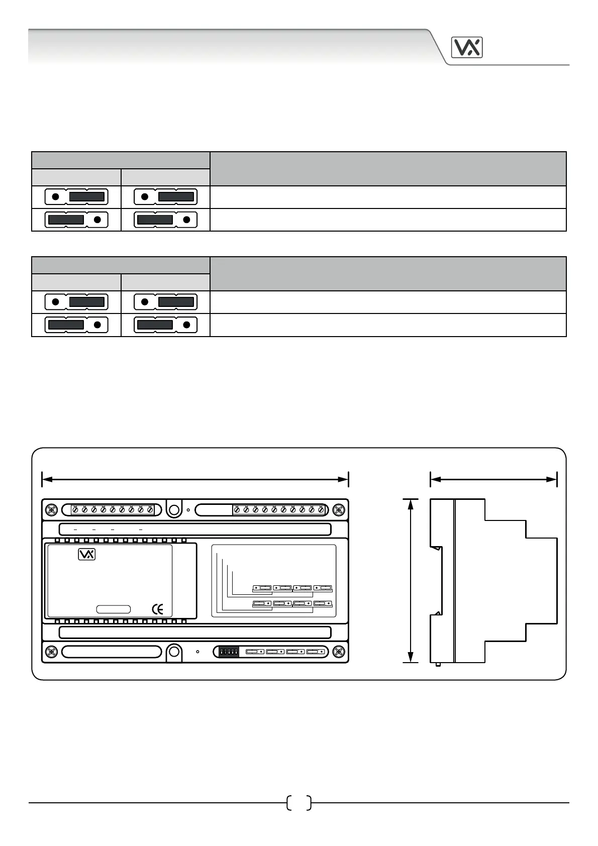
157.5mm 65mm
85mm
Art. VX2206N
Made in Italy
BLOCK CONTROLLER
VIDEX
2206N-1.41
SW1 JP5 JP4 JP3 JP2
Balanced Video Signal
75 Ohm Termination OFF
Coax Video Signal
75 Ohm Termination ON
2206N
JP5 JP4 JP3 JP2
V/V1P V2 V/V1 V2 V/V1V2PV/V1LV2LV/V10V20
+12BSBOLBMB
IMPORTANT NOTE: Further information regarding operation, programming and setup for the Art.2206N can
be found in the VX2200 technical manual ‘Edition 2014, Version 1.2.
Video Signal Mode using the Jumpers
The jumpers JP2, JP3, JP4 and JP5 are used for the video signal setup on the Art.2206N and consists of the
following settings:
JP2 and JP3 sets up the video signal.
Jumper Position
Operating Mode
JP2 JP3
Coax video signal (V/GND)
Balanced video signal (non-coax, V1/V2)
JP4 and JP5 sets up the video signal termination*.
Jumper Position
Operating Mode
JP4 JP5
75Ω (Ohm) video signal termination enabled
75Ω (Ohm) video signal termination disabled
*When two or more Art.2206N devices are used on the same system and the video signal is connected
between each Art.2206N in line then jumpers JP4 and JP5 must be set to the disabled position (to the left).
Only the last Art.2206N in line must have the jumpers set to the enabled position (to the right).
Art.2206N Dimensions