VX2300 2 Wire Video Digital System
PrtCode:VX2300_3_1.doc – Pag.29 04/09/2012 Rev.3.1
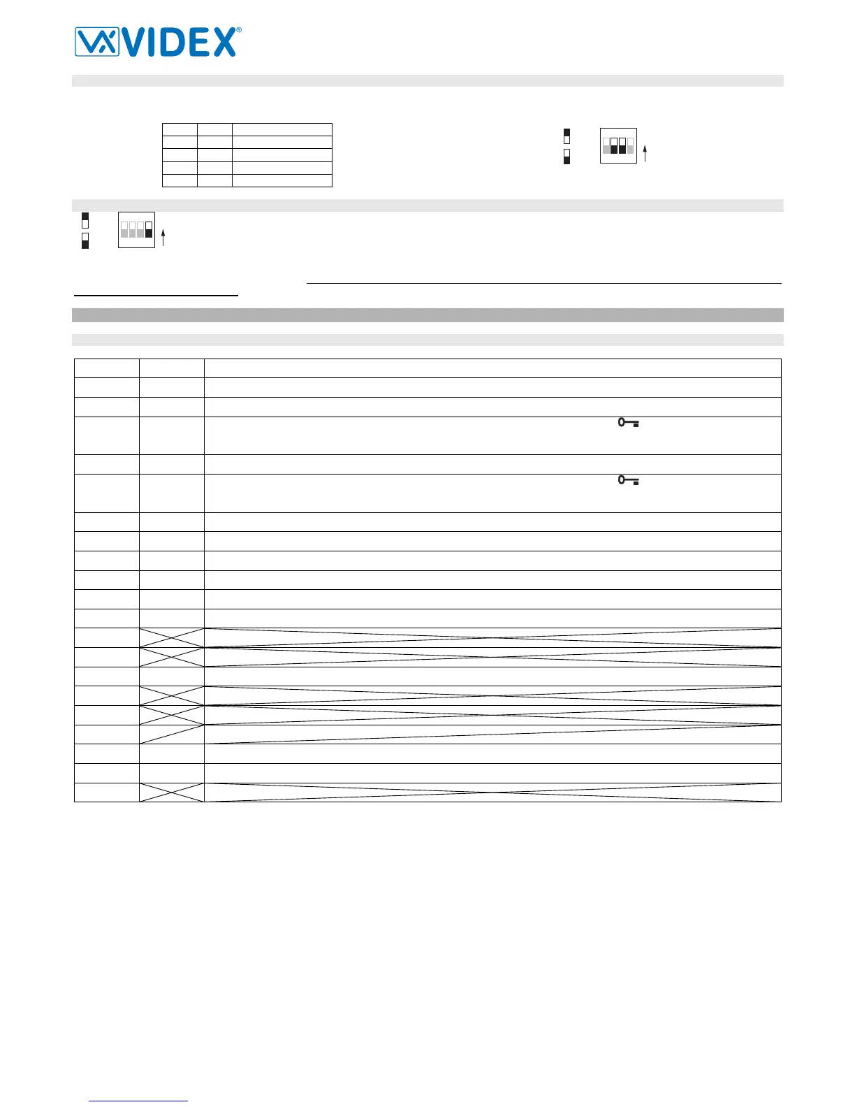
EXTENSION NO – SW3.2..3
If the intercommunication between apartments is enabled (switch 1 of SW3 = ON) leave these two switches in default position (both to OFF). Otherwise,
if the intercommunication is between the same apartment (switch 1 of SW3 = OFF), set the extension addresses starting always from 1. During the ex-
ternal call, all video monitors in the same flat will ring but the video will be shown only from the videmononitor with extension address 1.
2 3 Extension No.
OFF OFF 1 (default, master)
ON OFF 2 (slave)
OFF ON 3 (slave)
ON ON 4 (slave)
4
3
ON
2
1
=OFF
=ON
ON
SW3.2..3
SLAVE MODE - SW3.4
This set up concerns the answering mode of the video monitor when there is more than one unit (max 4) in the same apartment.
OFF (default) = during a call, only the video monitor with extension 1 (master) will show the video. ON = the video monitor will be
switched on independently of the extension address: in this case the video monitor must be supplied locally using a power sup-
ply Art.2321 and connecting respectively BUS+ to terminal 14 and BUS- to terminal 11 of the pcb connection board provided
with the Art.5980 (the local power supply is required for each black & white slave videophone or starting from the third slave vid-
eophone when are used all colour videophones). If you set ON this switch for one slave videophone, you must set ON the same switch also for
the relevant master videophone.
VIDEOMONITOR CONNECTION BOARD ART.5980
SIGNAL ON CONNECTION TERMINALS
Terminal Signal Description
1 GND
Ground
2 BUS1
Bus input
3 C
Dry contacts relay common contact (during a conversation, keep pressed the button
for more than 3 seconds to
enable the internal link between terminals “3” and “5” – the link remains until the button remains pressed) Max 50Vdc @
100mA
4 BUS2
Bus input
5 NO
Dry contacts relay common contact (during a conversation, keep pressed the button
for more than 3 seconds to
enable the internal link between terminals “3” and “5” – the link remains until the button remains pressed) Max 50Vdc @
100mA
6 DOL
Auxiliary LED power supply input (+12Vdc)
7 DOL
Auxiliary LED power supply input (ground)
8 GND
Ground
9 GND
Ground
10 LB
Local bell input (active low)
11 GND
Ground
12
13
14 +VAUX
Auxiliary power supply input (to be used when the switch 4 of SW3 is set to ON)
15
16
17
18 AL
Alarm input (not implemented yet)
19
AL-LB_GND
Ground output for use in combination with “AL” & “LB” active low inputs
20
4
3
ON
2
1
=OFF
=ON
ON
SW3.4
 Loading...


