16
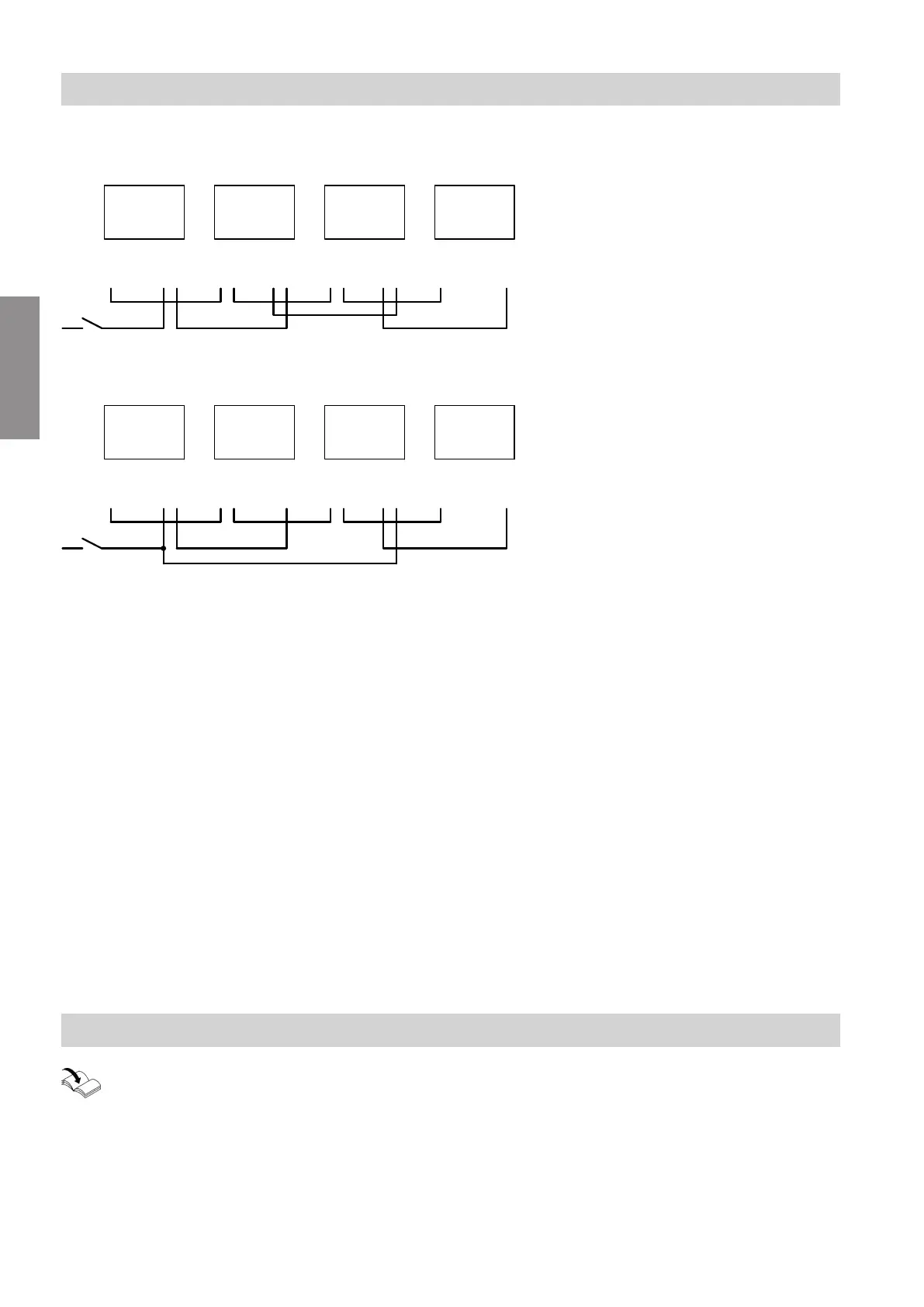
Power supply and PlusBus connection
Power supply to all accessories via heat generator control unit
74
74
40A
40
74
74
40A
40
B C
74
40
96/156
A
74
74
40A
40
D
E
Fig. 17
Some accessories with direct power supply
74
74
40A
40
74
74
40A
40
B C
74
40
96/156
A
74
74
40A
40
D
E
Fig. 18
A
Heat generator control unit
B
Mixer extension kit for heating circuit with
mixer M2 (ADIO electronics module)
C
Mixer extension kit for heating circuit with
mixer M3 (ADIO electronics module)
D
Further accessories
E
ON/OFF switch
fÖ
(A)
Power supply
jF
PlusBus
lH
/
aBH
Accessories power supply in the control unit of
the heat generator
■
In the following circumstances, use the output for the
accessories only to switch an on-site relay:
An actuator (e.g. circulation pump) with a higher
power demand than the fuse rating required for the
accessories is connected at the accessories output.
■
In the following circumstances, connect one or more
accessories directly to the mains supply via an
ON/OFF switch:
The max. permissible total current of the control unit
for the heat generator is exceeded.
Note
In this event, the accessories concerned cannot be
isolated with the ON/OFF switch on the control unit.
Commissioning
Heat generator installation and service instruc-
tions
Installation sequence
Connecting several accessories
5838001
Installation