24
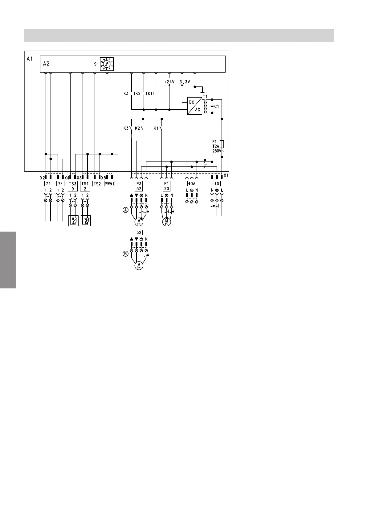
Fig. 23
A1 Mixer extension kit PCB
A2 PCB
F1 Fuse
S1 Rotary switch for subscriber number addressing
A
Mixer motor if wall mounted
B
Mixer motor if mixer mounted
230 V~ plugs
P1
sÖ
Heating circuit pump (on site)
P3
gS
Mixer motor
fÖ
Power supply 230 V/50 Hz
fÖ
A
Power supply for accessories
LV plugs
PWM1 No function
TS1
?
Flow temperature sensor
TS2 No function
TS3
)
Temperature sensor, low loss header
jF
PlusBus connection for connecting to the heat
generator and another accessory
Specification
Connection and wiring diagram
5838001
Appendix