8
L
?
N
?
N
jF jF
[{]
fÖ
M
1~
230 V~/50 Hz
M
1~
L
?
N
L
?
N
gS
sÖ
[{] [{] [{] [{{]
?
)
S1
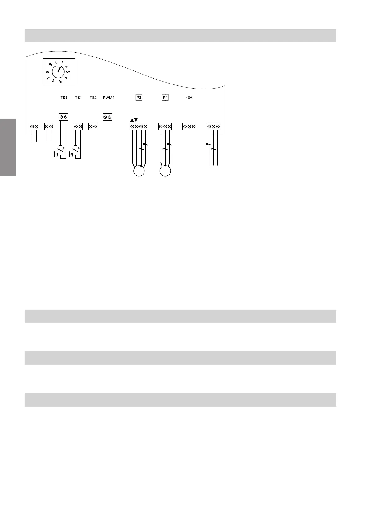
Fig. 4
Plug 230 V~
P1
sÖ
Heating circuit pump (on site)
P3
gS
Mixer motor
fÖ
Power supply
fÖ
A
Power supply for accessories
LV connections
PWM1 No function
S1 Rotary switch for subscriber number address-
ing
TS1
?
Flow temperature sensor
TS2 No function
TS3
)
Temperature sensor, low loss header
jF
PlusBus
!
Please note
Electronic assemblies can be damaged by elec-
trostatic discharge.
Prior to commencing any work, touch earthed
objects such as heating or water pipes to dis-
charge static loads.
Note
Apply strain relief to on-site cables.
Seal any unnecessary apertures with cable grommets
(not cut open).
Connecting the flow temperature sensor
Insert plug
?
at slot TS1 (see diagram 4).
Connecting the temperature sensor of the low loss header (if installed)
Insert plug
)
at slot TS3 (see diagram 4).
Connecting the mixer motor
Only in conjunction with extension kit for wall mounting
Installation sequence
Overview of electrical connections
5838001
Installation