6
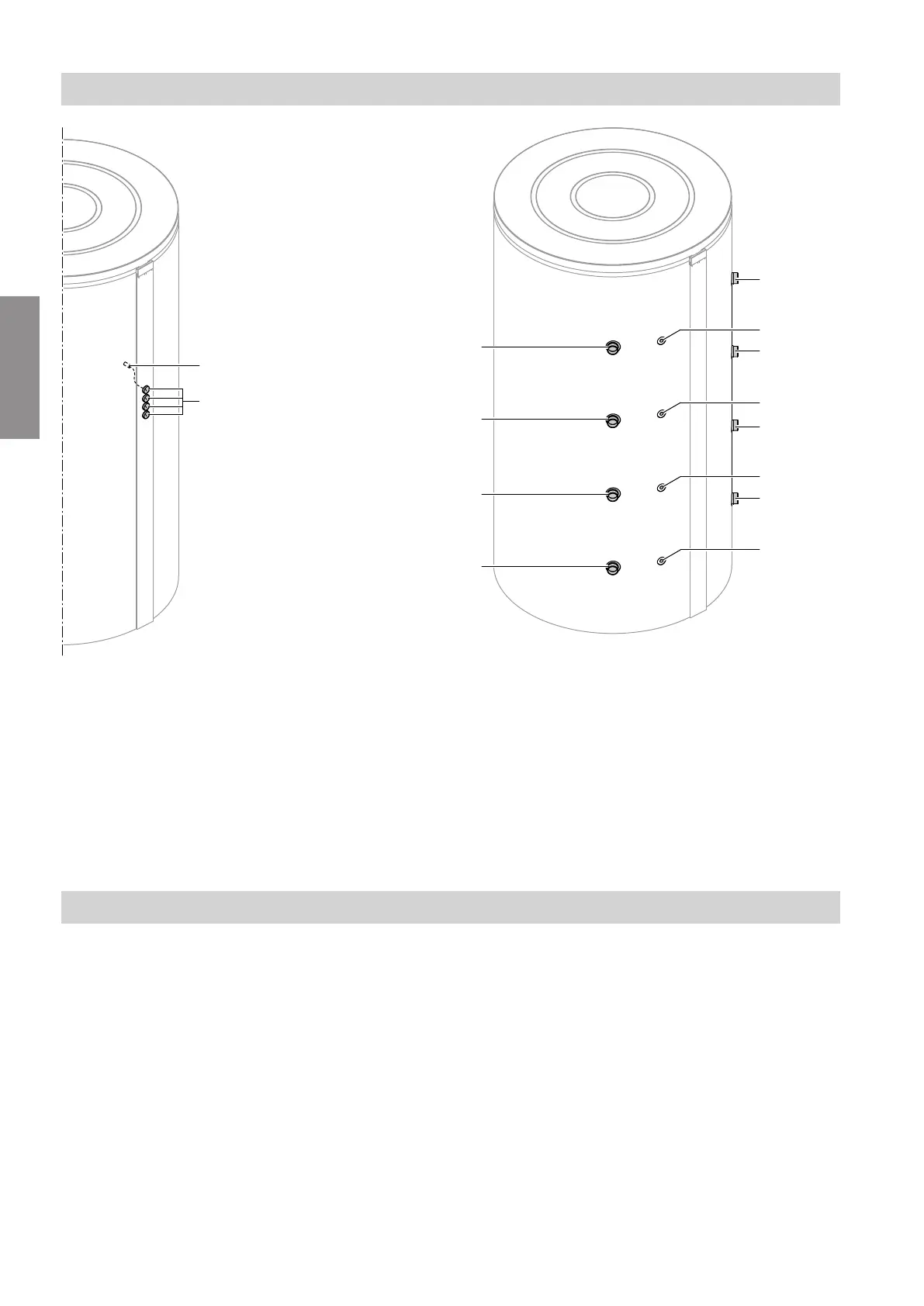
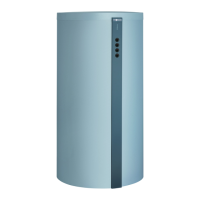
Fig. 1 Front
A
Thermometer sensor retainer
B
Max. 4 thermometers (TH, accessories)
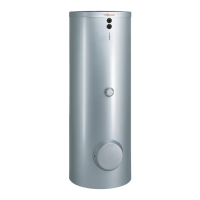
Fig. 2 Back
A
Heating water flow 1 (HF 1)
B
Heating water flow 2 (HF 2)/heating water return
(HR 1)
C
Heating water return (HR 2)
D
Heating water return (HR 3)
E
Sensor well for thermometer sensor (TR 1)
F
Sensor well for thermometer sensor (TR 2)
G
Sensor well for thermometer sensor (TR 3)
H
Sensor well for thermometer sensor (TR 4)
Siting
!
Please note
To prevent material losses, site the DHW cylin-
der in a room free from the risk of frost and
draughts.
Otherwise the DHW cylinder must be drained
when not in use and there is a risk of frost.
■
Provide adequate clearance from the wall to allow for
operation of the temperature controller (if installed).
■
Placing the cylinder on a plinth will make the room
easier to clean.
Preparing for installation
Connections
5694 385 GB
Installation