8
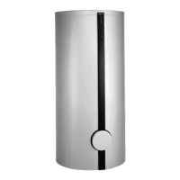
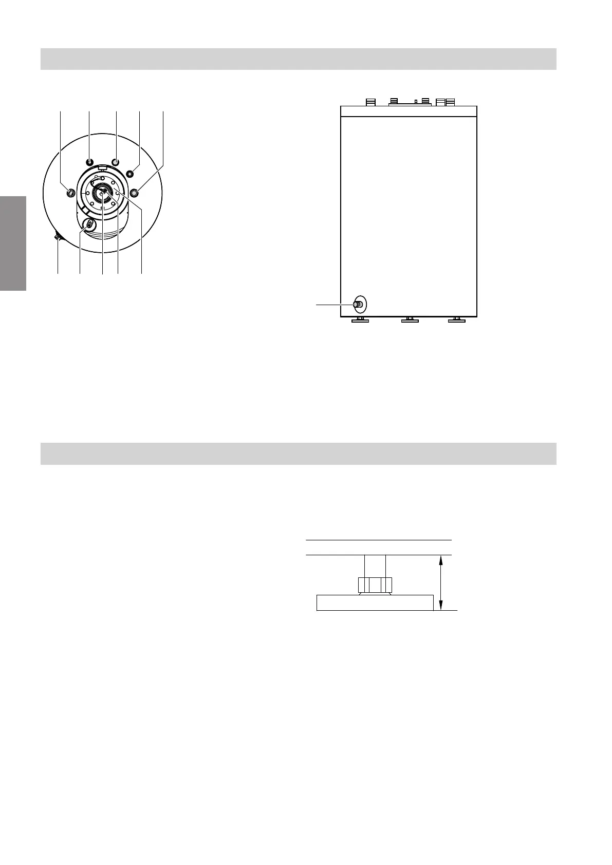
View from above
Fig. 2
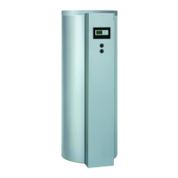
Front view
Fig. 3
A
Cylinder flow
B
DHW
C
Cold water
D
DHW circulation
E
Cylinder return
F
Inspection and cleaning aperture
G
Protective magnesium anode with earth cable
H
Connection, temperature sensor for thermometer
K
Sensor well for cylinder temperature controller
L
Drain
Siting the DHW cylinder
!
Please note
The thermal insulation must not come into con-
tact with naked flames.
Exercise caution when welding and brazing.
!
Please note
To prevent material losses, install the DHW cyl-
inder in a room free from draughts and risk of
frost.
When not in use, the DHW cylinder must be
drained if there is a risk of frost.
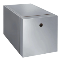
Use the adjustable feet to level the DHW cylinder.
Note
Only use one or two of the adjustable feet to level the
DHW cylinder. At least one of the adjustable feet must
remain fully screwed in.
Fig. 4
Never extend the adjustable feet beyond a total length
of 35 mm.
Preparing for installation
Connections
6150584
Service

 Loading...