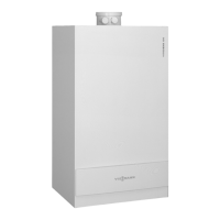
Flue gas header for several Vitodens – negative pressure
A
Flue gas
B
Ventilation air
Type B
23
, to CEN/TR 1749
Several boilers in the same room draw combustion air from the out-
side through vents and expel flue gas to the outside through a com-
mon flue pipe in the roof.
For a detailed description, see page 49.
Design and sizing information for connection on the flue gas side
2.1 Boiler allocation ― balanced flue pipe size
All details regarding length and cross-section in the following tables
are only valid in connection with the balanced flue components
offered in the Viessmann pricelist.
The specified system sizes are nominal diameters. Actual compo-
nent dimensions may differ.
Nominal diameter in mm Actual internal diameter in mm
Flue pipe Ventilation air
pipe
Flue pipe Ventilation air pipe
– Vitodens 100-W and Vitodens 111-W
– Vitodens 200-W up to 35 kW, Vitodens 222-W and
Vitodens 242-F
– Vitodens 300-W, Vitodens 333-F and Vitodens 343-F
– Vitosolar 300-F with Vitodens 300-W
60 100 60.5 +0.3 98.6 +0.3
– Vitodens 200-W, 49 to 60 kW 80 125 80.5 +0.8 126 ±0.5
– Vitodens 200-W, 69 to 150 kW 110 150 111 +1/-0.3 151 +0.8/-0.3
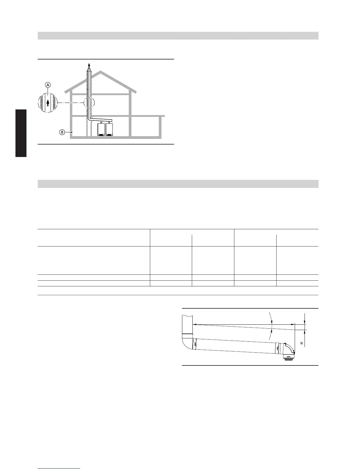
2.2 Installing flue pipes
When designing and installing the flue pipe, a fall of at least 3°
towards the boiler must be maintained.
The required fall is the same if using an 87° boiler flue connection
bend or 87° inspection tee.
The required fall of 3° also corresponds to a height differential of
approx. 50 mm over a length of 1 m.
If the required fall is not maintained, condensate will not drain off
fully and residue will remain in the joints. This will lead to an increase
in acid concentration and possible damage to the gaskets.
For this reason, the flue must also never be designed and installed
with a fall leading away from the boiler.
 Loading...