22
5601 189 v1.1
Vitodens 100-W, WB1B Technical Data
Model WB1B 26 35
∆ t
Output Btu/h 83,000 108,000
30° F rise (GPM) 5.5 ---
35° F rise (GPM) 4.7 6.2
40° F rise (GPM) 4.2 5.4
Maximum Flow Rates
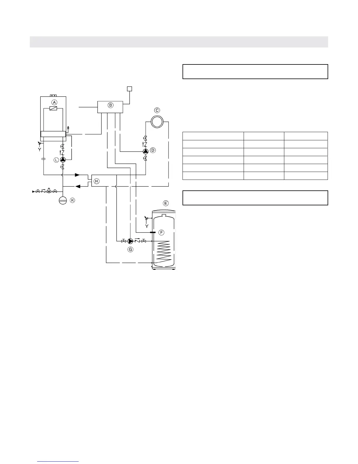
Vitodens 100-W, WB1B 10-26, 10-35 with DHW storage
tank and one heating circuit
Legend
AV Air vent
PRV Pressure relief valve
TPV Temperature and pressure relief valve
A
Vitodens 100-W gas-fired condensing boiler
B External boiler/DHW controller (field supplied)
C Heating circuit
D Heating circuit pump (field supplied)
E DHW storage tank
F DHW tank temperature aquastat or sensor
G DHW circulating pump (field supplied)
H Closely spaced tees, 4x pipe Ø or 12” (305 mm)*
K Expansion tank
L Primary pump (boiler circuit, field supplied)
with low-loss header only
* A low-loss header offers additional benefits not
provided by a pair of closely spaced tees.
Viessmann strongly recommends and prefers the
use of a low-loss header over closely spaced tees.
See page 18 for details.
IMPORTANT
IMPORTANT
Primary pump must pump into the boiler (as illustrated).
Note: The use of a low-loss header is recommended if the
water flow rate is less than 1.7 GPM (400 L/h) or
more than 6.2 GPM (1400 L/h).
T
he low-loss header is available as an accessory part.
DHW supply and return piping between boiler DHW
connections and the Viessmann DHW tank connections,
shall be a minimum of 1” nominal pipe diameter
(irrespective of the ¾” DHW connection outlet sizes
provided on the boiler and the DHW tank).
This ensures that the head of the pump is fully utilized
to overcome the resistance of the DHW heat exchanger
coil and to provide sufficient water flow to the boiler
heat exchanger.
In non-Viessmann DHW tank applications, perform, in
addition to the above, accurate calculations for DHW
tank coil pressure drop versus boiler pump head to
ensure sufficient water flow to the boiler heat exchanger.
Failure to heed the above instructions may cause boiler
short-cycling and inadequate DHW supply.
System Layout 3
Installation
AV
PRV
TPV
 Loading...