28
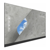
Detachable System Control Box
The System Control Box can be installed under the Cabinets (standard installaon)
for front access, or behind the Cabinets.
RS232
LAN
USB
5V/1.5A
USB
5V/1.5A
S/PDIF
OUT
AUDIO
IN
AUDIO
OUT
HDMI
OUT
IR IN
HDMI 5
(2.1)
HDMI 4
(1.4)
HDMI 3
(1.4)
HDMI 2
(2.0)
HDMI 1
(2.0)
POWER
USB A
USB C
POWER
HDMI
OUT
AUDIO
OUT
AUDIO
IN
S/PDIF
OUT
IR IN
USB
5V/1.5A
USB
5V/1.5A
LAN
HDMI 1
(2.0)
HDMI 2
(2.0)
HDMI 3
(1.4)
HDMI 4
(1.4)
HDMI 5
(2.1)
RS232
USB C USB A
Standard Installaon Hidden System Control Box Installaon
NOTE:
• Standard Installaon video.
• Follow the below guide to install the display with the Hidden System
Control Box layout.
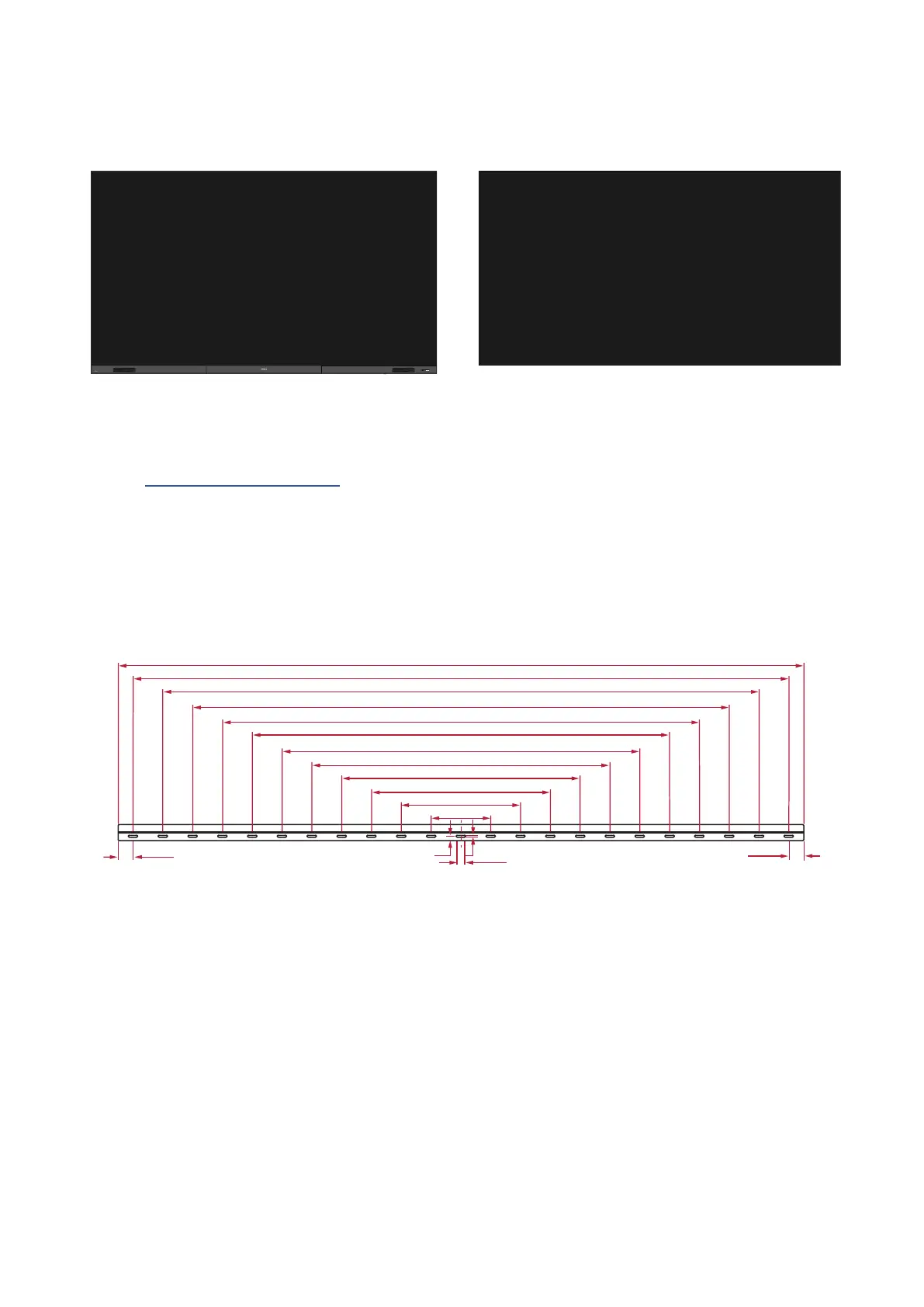
Wall Mounng
Installing the Upper and Lower Wall Mount Brackets
50.8 mm
50.8 mm
25.4 mm
7 mm
15 mm
203.2 mm
406.4 mm
609.6 mm
812.8 mm
1016 mm
1219.2 mm
1422.4 mm
1625.6 mm
1828.8 mm
2032 mm
2235.2 mm
1. Ensure the wall area and size is an appropriate installaon site.
NOTE:
The height of the Upper
Wall Mount Brackets
must not be less than 129
⁵⁹/₆₄" (3300 mm) from the ground.
2. Using the Wall Mount Bracket (pictured above) as a guide, mark at least 12 holes
and pre-drill them.