Introduction 7
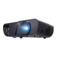
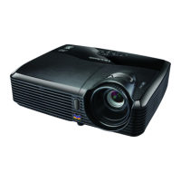
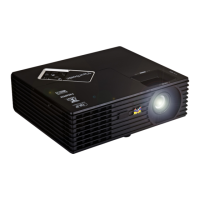
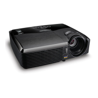
Projector exterior view
1. External control panel
(See "Projector and remote control"
on page 8 for details.)
2. Vent (heated air exhaust)
3. Quick-release button
4. Lens cover
5. Focus ring and Zoom ring
6. Front IR remote sensor
7. Projection lens
8. AC power cord inlet
9. RS-232 control port
10. RGB signal output socket
11. RGB (PC)/Component video
(YPbPr/YCbCr) signal input
socket-1
12. RGB (PC)/Component video
(YPbPr/YCbCr) signal input
socket-2
13. Video input socket
14. S-Video input socket
15. Audio signal input socket
16. Audio signal output socket
17. Kensington anti-theft lock slot
18. Quick-release foot
19. Lamp cover
20. Rear adjuster foot
21. Security bar
Connects a commercially available
theft prevention cable.
Warning
• THIS APPARATUS MUST BE EARTHED.
• When installing the unit, incorporate a readily accessible disconnect device in the fixed wiring,
or connect the power plug to an easily accessible socket-outlet near the unit. If a fault should
occur during operation of the unit, operate the disconnect device to switch the power supply
off, or disconnect the power plug.
Front/upper side
7
1
2
3
4
5
6
Rear/lower side
18 20
1714131110
9
8
19
15 1612
21