12
Wall Mounng
Refer to the table below for the standard dimensions for wall mount kits.
NOTE: For use only with a UL cered wall mount kit/bracket. To obtain a wall-
mounng kit or height adjustment base, contact ViewSonic® or your
local dealer.
Maximum
Loading
Hole paern
(W x H)
Interface Pad
(W x H x D)
Pad Hole
Screw
Specicaon
Quanty
14 kg 100 x 100 mm 115 x 115 x 2.6 mm Ø 5 mm M4 x 10 mm 4 screws
NOTE: Wall mount kits are sold separately.
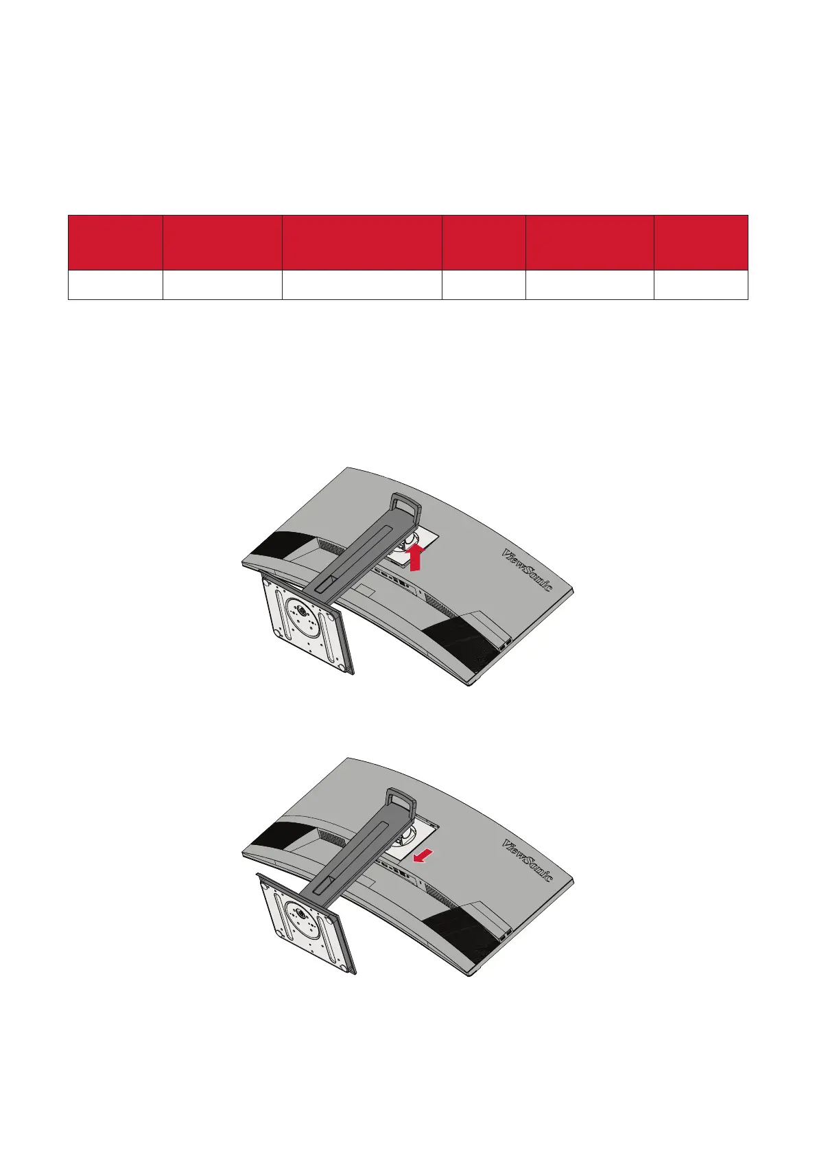
1. Turn o the device and disconnect all cables.
2. Place the device on a at, stable surface with the screen facing down.
3. Push and hold the quick release tab and carefully li the stand.
4. Pull down slightly to disengage the hooks and remove the stand.