EasyManuals Logo

Viking DEVDSC305 Installation Guide

Viking DEVDSC305
20 pages
To Next Page IconTo Next Page
To Previous Page IconTo Previous Page
Page #16 background imageLoading...
Page #16 background image
15
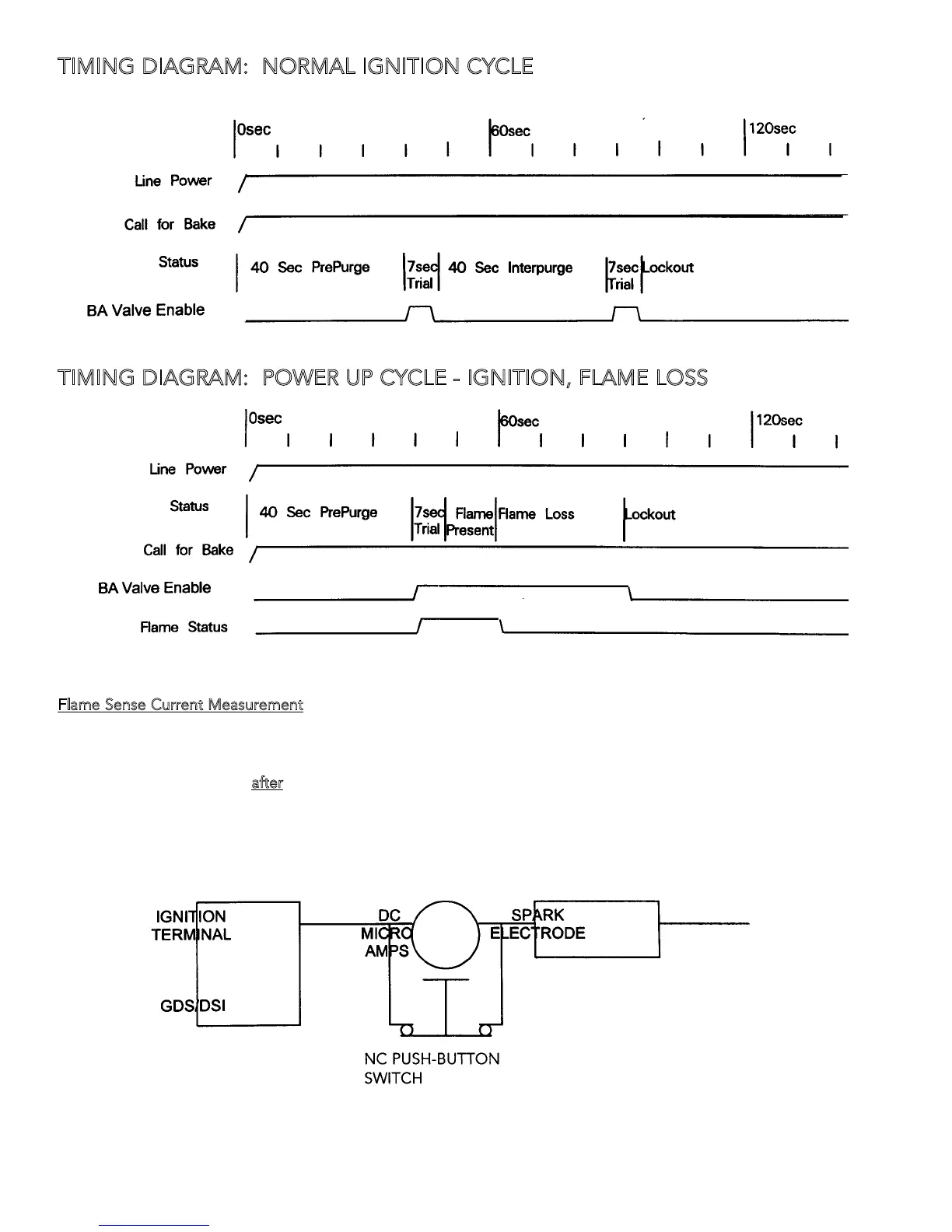
TIMING DIAGRAM: NORMAL IGNITION CYCLE
TIMING DIAGRAM: POWER UP CYCLE - IGNITION, FLAME LOSS
Flame Sense Current Measurement
Local Sense:
Connect a DC Micro-amp meter in series with the high voltage lead and the spark electode wire as shown.
Push switch to read current
a
fter
flame is established and the spark output is de-energized.
LOCAL SENSING: CONNECT DC MICRO-AMP METER IN SERIES WITH HIGH VOLTAGE LEAD AS SHOWN
PUSH SWITCH TO READ CURRENT AFTER FLAME
IS ESTABLISHED AND SPARKING CEASES

Other manuals for Viking DEVDSC305

Questions and Answers:

Question and Answer IconNeed help?

Do you have a question about the Viking DEVDSC305 and is the answer not in the manual?

Viking DEVDSC305 Specifications

General IconGeneral
BrandViking
ModelDEVDSC305
CategoryRanges
LanguageEnglish

Related product manuals