Disassembly
©2012 Viking Preferred Service 15
WARNING!
Overlay Switch
Release tab and pull
connector out of socket.
To avoid risk of electrical shock, personal injury, or death, disconnect electrical power source to unit, unless
test procedures require power to be connected. Ensure all ground wires are connected before certifying unit as
repaired and/or operational.
1. To replace the overlay switch, remove
the upper air grille assembly, remove the
control panel (see Air Grille and Control
Panel Removal sections, Page 14).
2. Disconnect overlay switch from control.
The unit uses an overlay switch to
communicate user input to the control boards.
The overlay connects to the control board via
a ribbon cable.
Overlay Switch
9. Reverse procedure to reinstall
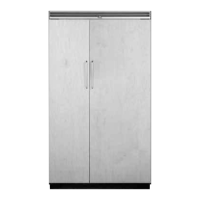
8. The control panel can now be removed
and the high voltage and low voltage
boards are accessible
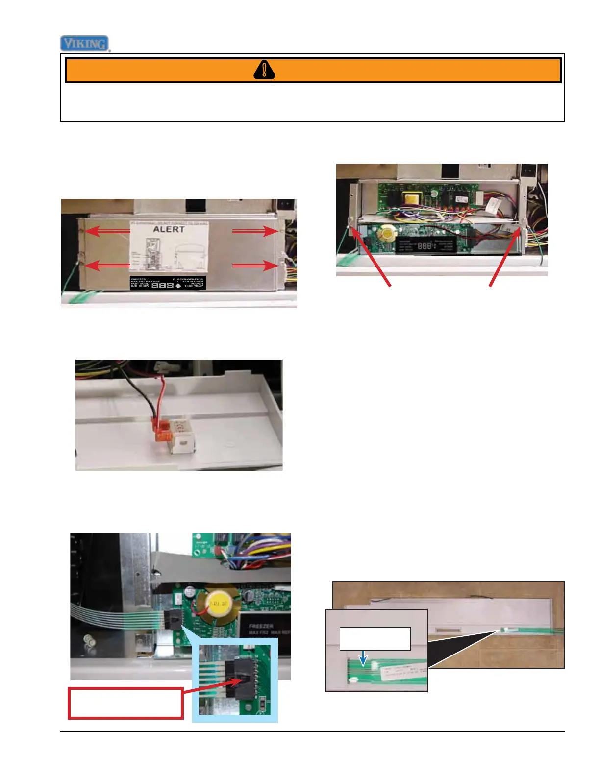
7. Remove the two strain relief screws.
6. Disconnect the ribbon from the control
board.Take caution with the ribbon cable
to prevent damage.
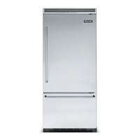
5. Disconnect the door switch from the back
of the control panel.
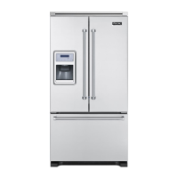
4. Remove the four screws securing the
control board cover. Remove control
board cover.
Control Panel (continued)