Diagnostics
48 ©2012 Viking Preferred Service
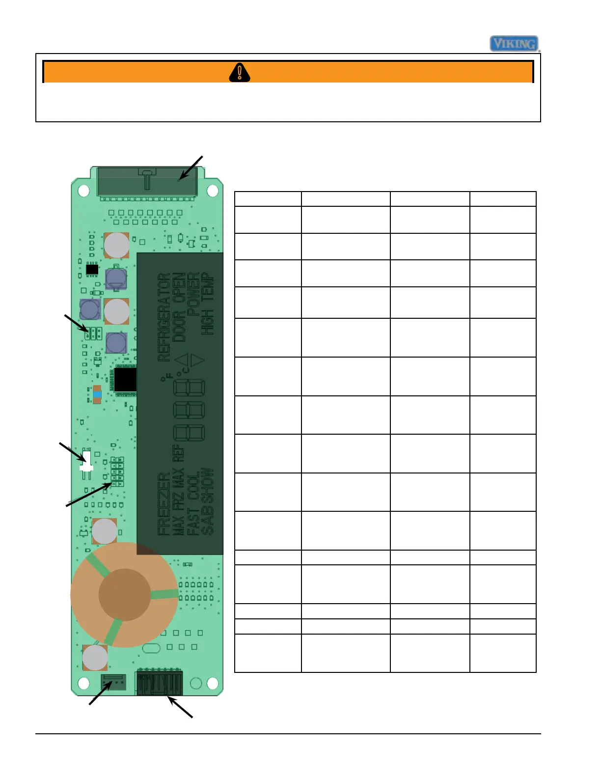
P4
P9
P5
P8
P3
J7
Pin location Function Voltage range Signal
P4-1 Dc supply to
thermistors
4.5 - 5.5 VDC,
ref to P4-12
DC
P4-2 Freezer thermistor
input
0 - 5.5 VDC, ref
to P4-12
DC
P4-3 Refrigerator
thermistor input
0 - 5.5 VDC, ref
to P4-12
DC
P4-4 Provide zero
timing
26 V p-p to 34V
p-p, ref P4-12
See Note 1
below
P4-5 DC Fan enable 17.8 vdc - 38
vdc, ref to
chassis grnd.
DC
P4-6 Defrost
termination
17.8 vdc - 38
vdc, ref to
chassis grnd.
See Note 2
below
P4-7 Evaporator fan
enable
17.8 vdc - 38
vdc, ref to chas-
sis ground
See Note 2
below
P4-8 Compressor
enable
17.8 vdc - 38
vdc, ref to chas-
sis ground
See Note 2
below
P4-9 Defrost termina-
tion signal
25.8 vdc - 38
vdc, ref to chas-
sis grnd
See Note 2
below
P4-10 Door signal 25.8 vdc - 38
vdc, ref to chas-
sis grnd
See Note 2
below
P4-11 PS Reference 0 vdc DC
P4-12 -30 vdc 22.8 vdc - 38
vdc, ref to chas-
sis ground
See Note 2
below
P4-13 Not used AC
P4-14 Not used AC
P4-15 Light enable relay 17.8 vdc - 38
vdc, ref to chas-
sis ground
See Note 2
below
Low Voltage Board
NOTE 1 : Requires an oscilloscope to measure
NOTE 2 :DC voltage- load of meter can affect measurement
To avoid risk of electrical shock, personal injury, or death, disconnect electrical power source to unit, unless test
procedures require power to be connected. Discharge capacitor through a resistor before attempting to service.
Ensure all ground wires are connected before certifying unit as repaired and/or operational.
WARNING!