EasyManua.ls Logo

Viking VGSO100 User Manual

Viking VGSO100
24 pages
To Next Page IconTo Next Page
Page #1 background imageLoading...
Page #1 background image
Service
Manual
30” Gas
Single Wall Oven
Preferred Service
VGSO100
SMC-0006A
Feb 2012
®
This manual is to be used by qualied appliance technicians only. Viking
does not assume any responsibility for property damage or personal
injury for improper service procedures done by an unqualied person.
This Base Manual covers general and
specic information including, but not
limited to the following models:

Other manuals for Viking VGSO100

Question and Answer IconNeed help?

Do you have a question about the Viking VGSO100 and is the answer not in the manual?

Viking VGSO100 Specifications

General IconGeneral
TypeSingle Oven
Fuel TypeGas
Oven Capacity4.7 cu. ft.
ConvectionYes
Self-CleaningYes
Interior LightYes
Width30 inches

Summary

Important Information and Safety

Safety Alert Symbol Definitions

Explains Danger, Warning, and Caution symbols and their meanings.

Technical Support Contact Information

Provides contact details for service support and correspondence.

General Information - Safety and Requirements

General Warnings and Hazards

Crucial safety advice on fire, electrical shock, and gas leaks.

Electrical Requirements

Specifies voltage and frequency needs for the appliance.

Gas Connection and Handling

Manual Shut-Off Valve and Pressure Regulator

Requirements for gas shut-off valves and pressure regulator settings.

Flexible and Rigid Gas Connections

Guidelines for connecting the gas supply lines.

Appliance Handling and Usage Warnings

Warnings against using the appliance as a heater or lifting by the door.

Model and Serial Number Identification

Model Number Breakdown

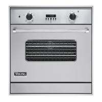
Explains the structure and meaning of the model number.

Serial Number Format and Location

Details the format and location of the serial number.

Operation - Controls and Cycles

Oven Main Panel Controls Overview

Describes the function of interior lights, timing center, and temperature controls.

Cooking Cycle Descriptions

Explains the use of Bake, Convection Bake, Broil, and Convection Broil functions.

Cooking Cycle Details

Natural Airflow Bake Function

Details natural airflow bake operation and applications.

Broil and Convection Broil Functions

Explains broil functions and their benefits like smoke reduction.

Convection Bake Function Operation

Describes convection bake benefits for even heat distribution.

Service Procedures Overview

Service Situation Chart

Overview of component serviceability and accessibility.

Service Procedures - Control Panel

Control Panel Component Locations

Identifies Main Control, Selector Switch, and Thermostats.

Service Procedures - Rear Oven

Rear Oven Component Locations

Identifies Power Cord, DSI Module, and Solenoids in the rear.

Service Procedures - Top Section

Top Section Component Locations

Identifies blowers, high limit, and fan switch in the top section.

Service Procedures - Main Oven

Main Oven Component Locations

Identifies Bake and Broil Burners and Igniters.

Door Service Procedures

Oven Door Removal

Step-by-step guide for safely removing the oven door.

Oven Door Reinstallation

Instructions for correctly reinstalling the oven door.

Component Testing Procedures

RTD Sensor Testing and Chart

Provides temperature-to-resistance chart and RTD testing method.

Other Component Test Locations

Lists components, readings, and test points.

Troubleshooting Guide

Common Oven Problem Diagnosis

Lists problems, causes, and corrections for oven operation.

Component Specific Procedures

RTD Sensor Function and Testing

Explains RTD's role in temperature measurement and testing.

Oven Cavity Light Replacement

Details how to access and replace oven interior lights.

Component Specific Procedures

High Limit Thermostat Operation

Describes the location and operation of the high temperature limiter.

Cooling Fan Switch Function

Explains how the cooling fan switch activates the fan based on temperature.

Convection Fan Motor Operation

Details the convection fan motor's power source and access procedure.

Component Specific Procedures

Main Control Unit Operation

Explains main control operation and access.

Electronic Thermostat Function

Describes thermostat role in temperature control and access.

Component Specific Procedures

Selector Switch Function and Access

Explains selector switch operation and access.

DSI Module Function and Operation

Details Direct Spark Ignition module's role in burner ignition.

Component Specific Procedures

DSI Module Testing Procedures

Provides step-by-step instructions for testing the DSI module.

Component Specific Procedures

Bake and Broil Solenoid Functionality

Explains solenoid function and voltage requirements.

Bake and Broil Solenoid Resistance Test

Details how to test the resistance of the solenoids.

Wiring Diagrams

Wiring Diagram - Units Before Serial # 072711C00029673

Presents the electrical schematic for earlier models.

Wiring Diagrams

Wiring Diagram - Units After Serial # 072711C00029673

Presents the electrical schematic for later models.

Related product manuals