Service Procedures
©2012 Viking Preferred Service 17
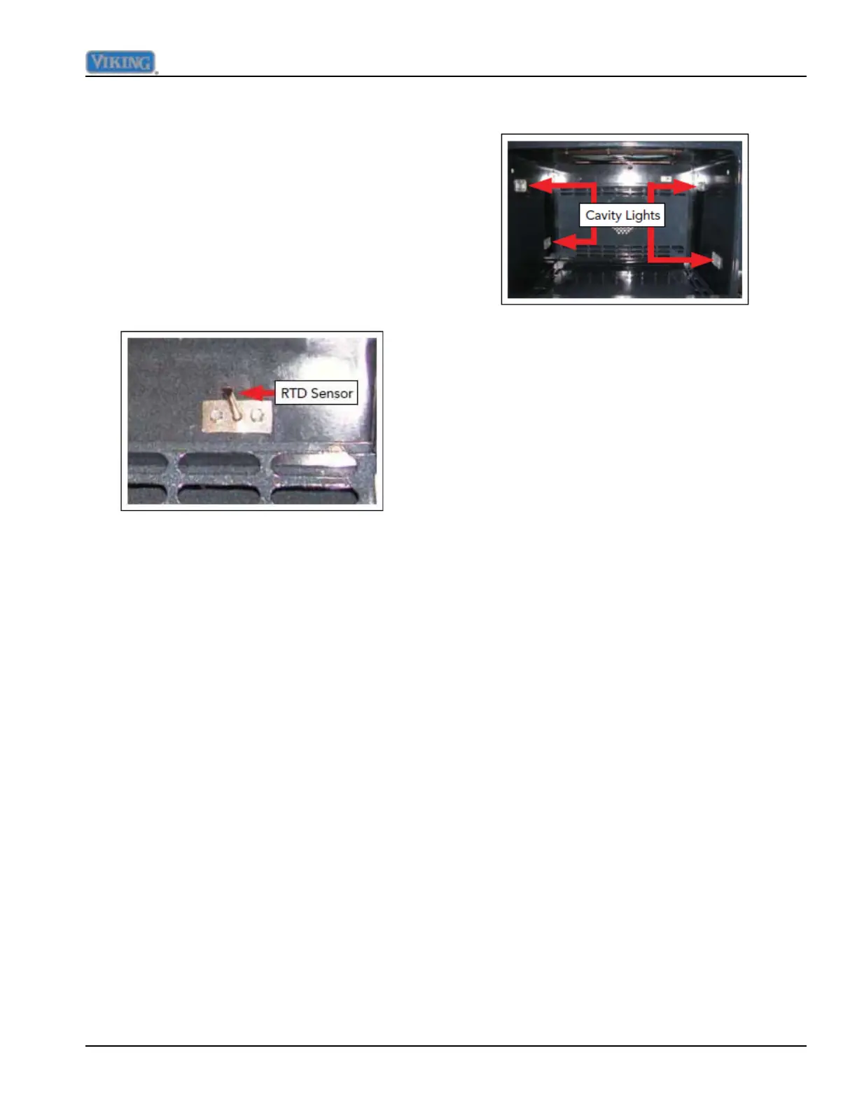
RTD Sensor
The oven utilizes an RTD (Resistance
Temperature Detectors) to measure the
temperature in the oven cavity. As the
temperatures rise and fall, the resistance
in the RTD changes. These changes are
interpreted by the Main Control, thus
controlling the bake and broil burners. As the
temperature rises, the resistance increases.
Page 18 shows the ratio of temperature to
resistance.
To access the RTD sensor, locate the sensor
at the upper rear wall of oven cavity. Remove
securing screws and gently pull the sensor
forward. The RTD has a Molex connector
that once disconnected allows testing of the
sensor. With the sensor disconnected and
Volt-Ohm Meter set to Ohms, record the
sensor resistance. At room temperature the
resistance should be approximately 1050
ohms. If the resistance reading is zero ohms
or extremely high, replace the RTD. If the
readings are within range, ohm each wire to
ground. If resistance is present, then the RTD
is grounded and the physical wires must be
checked for a grounded connection. If the
RTD resistance is within range and the wires
are not grounded, the RTD is functional and
should not be replaced.
Note: When reinstalling the sensor, make
sure the wire is pushed completely through
insulation blanket. Failure to get the wires
through the insulation blanket can overheat
the wires resulting in defective wires.
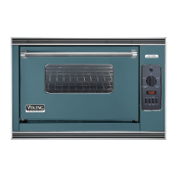
Cavity Lights
The oven utilizes 120 volt Halogen bulbs
to illuminate the oven cavity. The lights are
switched on by depressing the oven light
switch on the control panel.
To access the cavity lights, locate in the oven
cavity. Remove the screws securing the lens.
Remove the bulb from the socket once cool.
With Volt-Ohm Meter set to Ohms, measure
the resistance across the socket terminals
(white/red to white/blue). If resistance is
found, the socket and wiring is good and the
bulb should be replaced. If no resistance
is found, check the wiring for a short or break.
If wiring is good, the problem lies in the
socket


 To Next Page