11
a
7511001
WARNING: The lock must only be released with
the key when the platform is at the destina¬tion fl oor.
Close the gate and call the after-sales service.
8) SAFETY SYSTEMS
a) Safety nut screw
This is a second nut screw which only comes into
op¬eration if the main one is no longer engaged with the
lifting worm screw. If the safety nut screw is engaged,
a electrical failure detection system will prevent the
platform from being used until it is repaired.
b) Locks
Use of the platform is only enabled with the correct lock
status; the unit cannot be used if the gates are open or
the locks have been tampered with.
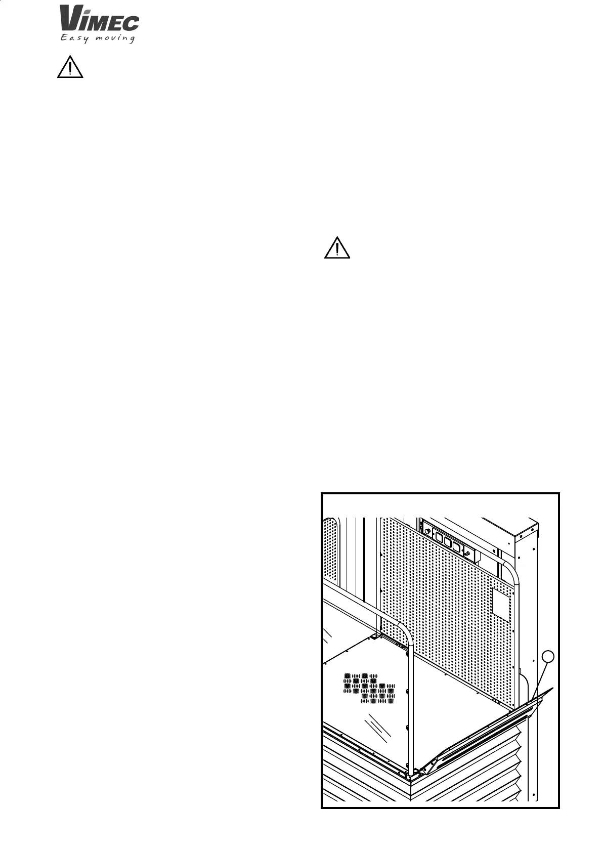
c) Flap
The platform is fi tted with a fl ap (Fig. 10/a) which has
the dual function of acting as an access ramp at the
fl oors (when lowered) and holding the wheelchair in
place while the lift is in motion. The fl ap automatically
moves to the safety position once the platform has risen
a few centimetres above the bottom fl oor.
The fl ap only opens at the bottom fl oor.
8.1) Other Safety Devices
a) Limit switches and limit stops
The limit switches stop the lift automatically in the
embarkation and disembarkation positions when it
reaches the fl oors.
b) Anti-shearing/anti-crushing guard
The platform is always fi tted with a bellows guard on
the open sides.
c) Power Supply
The unit is supplied at 230 V VAC single-phase (50
Hz), while the auxiliary circuit and buzzer are supplied
at 24 VDC.
d) Controls
All the controls are of hold-to-run type (the lift stops as
soon as the fi nger is removed from the button).
The control boards at the fl oors are enabled by a
remov¬able key. The platform is not accessible until
the gates have been opened (no-one can use the unit
unless the key is inserted).
FIG.10
e) Operation by hand
The lift can always be raised/lowered by hand to bring
the passenger to the fl oor in the event of a system failure
or power blackout. (See point 7.10).
f) Emergency stop button
There is a red emergency STOP button on board the
platform. When pressed, the emergency STOP button
cuts out all lift movements and triggers the alarm sy-
stem.
To restore the lift to operating mode, turn the STOP
button clockwise through 45°.
WARNING: Check operation of the emer-
gency STOP button every month. If the STOP button
does not cut out all lift movements, DO NOT USE
the lift!!
Call in an authorised VIMEC technician at once.
g) Movement cut-out in the event of obstacles
The platform is fi tted with a sensor which automatically
cuts out downward movement in the event of obstacles
interfering with the moving parts underneath it.
7512001