Do you have a question about the vimec S10 and is the answer not in the manual?
Details the S10 Model and the manual's sections: Use, Maintenance, and Parts Catalogue.
Provides VIMEC s.r.l.'s address, phone, fax, and website for inquiries.
Identifies VIMEC S.r.l. and the person authorized to compile the technical file.
Lists the EC directives the lift conforms to, including EMC and Low Voltage.
Highlights critical safety warnings and general precautions for lift users.
Defines the required skill levels: Trained Operator (TO) and Skilled Operator (SO).
Shows details from the lift's identification plate: Type, Load, Power, Serial Number.
Placeholder for dealer stamp and authorized service contact information.
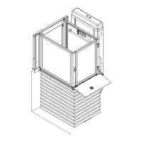
Describes the platform, column, gates, and nameplate.
Details the motor, worm, screw, and brake of the lifting system.
Explains the buttons and keys found on the control panels.
Covers safety aspects like gates, over-run devices, stop buttons, and micro-safety.
Describes the warning signs related to payload and permitted users on the lift.
Lists the key European directives the lift complies with.
Defines the correct applications and explicitly forbidden operations of the lift.
Specifies speed, payload capacity, and duty cycles.
Details operating temperature, voltage, and IP protection rating.
Explains the hold-to-run controls and key-enabled floor operations.
Outlines customer responsibilities for power supply and lighting setup.
Covers powering up the lift and essential checks before operation.
Instructions for using the key-switch and call button at floors.
Details key insertion and button operation for lift travel.
Explains the function of the emergency stop button and alarm buzzer.
Guidelines for securing keys and storing manual documentation.
Specifies required skill level (TO) and crucial power-off warning.
Step-by-step guide for manual recovery, including using the handwheel.
Details safety nut screw, locks, and platform flap functions.
Covers limit switches, anti-shearing guards, power supply, and controls.
Explains the emergency stop button and downward movement obstacle detection.
Advises regular inspections by qualified technicians for safe operation.
Lists components and checks required at specific intervals (6 months, 12 months, installation).
Explains how nut wear occurs and how to measure it.
Defines when nuts need replacement and the steps for measurement.
Lists common problems like platform not moving and their possible causes/remedies.
Indicates where wiring diagrams are located and provides vibration/noise level information.
Provides guidance on the proper disposal of lift components and materials.
Lists the components included in the lift's supply package.
Covers suitable installation locations and procedures for transport and storage.
Details essential checks before starting installation, such as dimensions and voltage.
Describes how to lift and position the column, checking for verticality.
Instructions for fixing the column to the wall using plugs and brackets.
Details assembling connections and mounting guide tracks for strokes over 1600mm.
Procedures for checking guide alignment and critical distance measurements.
Instructions for fixing the head connection, ensuring perpendicularity with L brackets.
Describes the head connection's pre-installed motor and electric panel.
Steps for mounting the trolley onto the column guides.
Instructions for fixing the "C" guides and side casings.
Steps for inserting the screw and connecting it to the trolley and nuts.
Details the installation of the transmission shaft and bearing group.
Procedures for raising and positioning the platform, and managing bellows.
Instructions for assembling the edge guards onto the platform.
Attaching hinges to the platform slide.
Mounting the push-button panel support and the panel itself.
Steps for fixing the frontal casings.
Procedures for installing the upper floor gate and fixing it to the ground.
Steps for connecting wiring, power supply, and motor/sensor to the main sheath.
Instructions for installing the long, short, and upper casings.
Procedure for mounting the slide cam to the column side casing.
Covers static, dynamic, control, and safety function tests.
Verifies correct operation of parts, sensors, fasteners, and door release.
Visual diagram illustrating the parts of the column assembly.
Provides a detailed list of parts for the column with codes and descriptions.
Visual diagram illustrating the parts of the casing.
Provides a detailed list of parts for the casing with codes and descriptions.
Visual diagram illustrating the parts related to nuts.
Provides a detailed list of parts for nuts with codes and descriptions.
Visual diagram illustrating rails and related accessories.
Provides a detailed list of parts for rails and accessories.
Visual diagram illustrating the on-board control panel components.
Provides a detailed list of parts for the on-board control panel.
Visual diagram illustrating the floor control panel components.
Provides a detailed list of parts for the floor control panel.
Visual diagram illustrating the lock assembly components.
Provides a detailed list of parts for the lock with codes and descriptions.
Visual diagram illustrating the bellows components.
Provides a detailed list of parts for the bellows with codes and descriptions.
Visual diagram illustrating the platform components.
Provides a detailed list of parts for the platform with codes and descriptions.
Visual diagram illustrating the electrical system components.
Provides a detailed list of parts for the electrical system.
Visual diagram illustrating the flap components.
Provides a detailed list of parts for the flap with codes and descriptions.
Visual diagram illustrating the on-board guards components.
Provides a detailed list of parts for the on-board guards.
Visual diagram illustrating the gate spring components.
Provides a detailed list of parts for the gate spring.
Visual diagram illustrating the motor-operated gate components.
Provides a detailed list of parts for the motor-operated gate.
Visual diagram illustrating the gate control board components.
Provides a detailed list of parts for the gate control board.
Visual diagram illustrating the remote call column components.
Provides a detailed list of parts for the remote call column.
| Brand | vimec |
|---|---|
| Model | S10 |
| Category | Lifting Systems |
| Language | English |