18
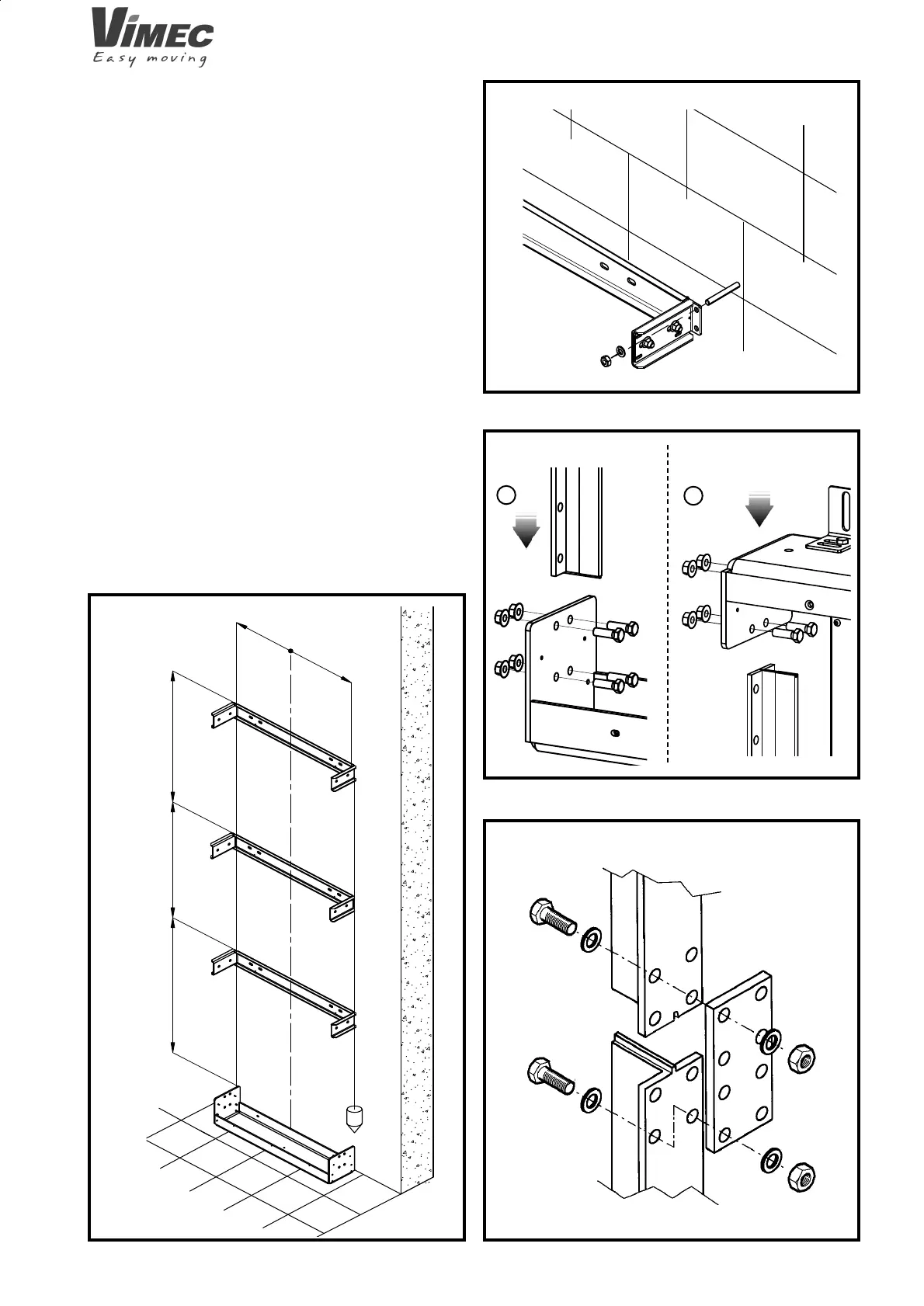
FIG.6
FIG.7
= =
XX
XX
XX
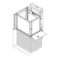
FIG.8
a
b
7511001
4.2 Wall assembly of the column for a machine with
a stroke above 1600 mm
Assemble the connections as follows:
With chemical or mechanical plugs:
- Fix the basic connection to the wall.
- Fix all the other intermediary connections making sure
that they are perfectly plumb and aligned with the fi rst
ones that were mounted (Fig. 5). If anything is out of
plumb, adjust it before tightening the wall plugs - (Fig.
6). Proceed with mounting the guide tracks:
N.B: The “T” tracks have a groove at one end; make
sure that the lower ones appear this way in the upper
part (Fig. 8).
- Mount the guides starting from the lower connection
(Fig. 7/a).
- Mount the remaining guide sections joining the plates
to be bolted - Fig. 8.
- Check the orthogonality of the guides (Fig. 9) before
tightening all the clamps on the connections.
- Also make spot checks of the distance between the
guides measured from the outside, which must be 900
± 0.5 mm.
- Take the head connection to the top of the guides and
use the 4 screws to fi x it to the guides (Fig. 7/b).
FIG.5
7512001