16
a
a
a
b
c
7511001
1. LIFT SUPPLY PACKAGE
Machine with 1100/1600 mm stroke
- Complete platform
- Preassembled column
- Upper fl oor gate complete with controls
- Panelling
- Remote call column (OPT)
Machine with stroke greater than 1600 mm
- Complete platform
- Decomposed column
- Upper fl oor gate complete with controls
- Panelling
- Remote call column (OPT)
2. PLACE OF INSTALLATION
The lift may be installed INDOORS or OUTDOORS.
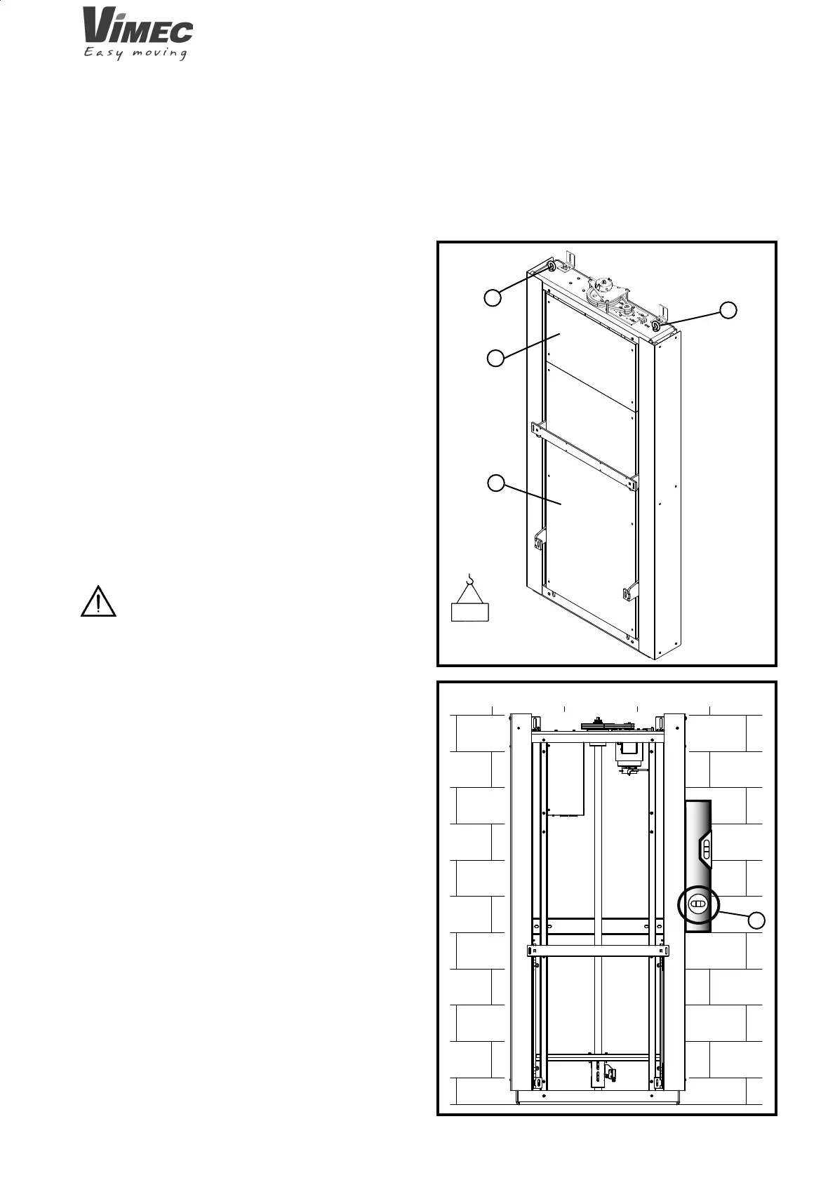
3. TRANSPORT
3.1) Handling
The lift, disassembled and on a pallet, must be handled
with the aid of suitable lifting equipment with rated load
at least 250 kg (Fig. 1).
Follow the instructions provided in chap. 4
of the assembly manual with regard to the correct
procedures for lifting and positioning the unit.
3.2) Storage
- Store the unit in a dry place
- Protect from dust with PVC sheeting.
FIG.1
FIG.2
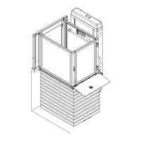
4. INSTALLATION INSTRUCTIONS
- Check that the lift and shaft dimensions are as stated
on the installation drawings.
- Check that the mains voltage specifi cations correspond
to those stated on the lift’s nameplate.
- Check that raceways have been provided for the power
supply cables and that a water drainage pit has been
constructed if necessary.
- Check that the base plinth on which the lift is to rest
is level.
- Place the lift in the intended position, with the distances
from the wall shown in the installation diagrams.
4.1 Wall column assembly for a machine with a
stroke under 1600 mm
- Use the eyebolts to remove the column from the
packaging and from the crate (Fig.1/a) and remove
any front casings (Fig. 1/b-1/c).
250 kg
7512001