21
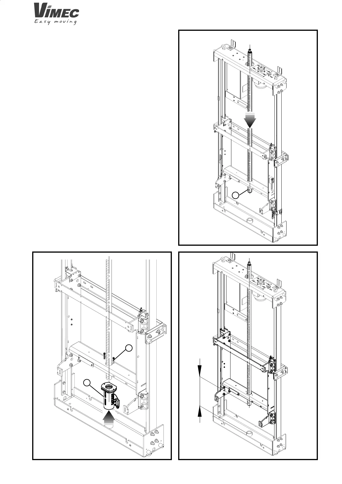
FIG.15
a
FIG.16
≈ 400
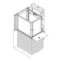
FIG.17
b
a
7511001
4.3 Mounting worm screws and nut screws
- Put the screw in the column and cross through the
hole in the trolley with the lower part of the screw
(Fig. 15/a).
- Raise the trolley and lift the screw about 400 mm,
(the screw will stick out from the upper support)
(Fig. 16).
- Put the trolley led nuts in from below (Fig. 17/a);
the holes must coincide with the 2 screws
on the trolley (Fig. 17/b).
- Then lower the trolley connected to the nut screw.
- Lower the screw, turning it to the nut screw (Fig. 18).
- From above insert the group of bearings that con-
tains the transmission shaft (Fig. 19/a).
- Screw the upper end of the screw to the hub of the
transmission shaft and make holes in them together
with a Ø4 tip (Fig. 20).
- Insert the M4 screw and self-locking nut (Fig. 21/a).
7512001
 Loading...