26
X
0
5:5
X
0
5:7
+
-
X01
:5
X01
:7
X
0
1:13
X01:15
X01:1
1
X
0
1
:9
2
1
3
4
5
6
C
a
7511001
FIG.31
FIG.33
FIG.30
FIG.32
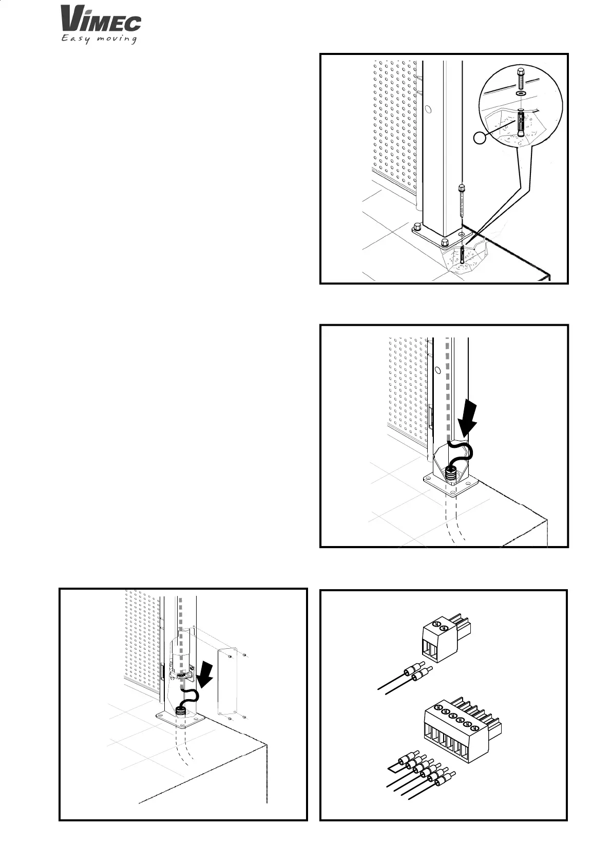
4.8 Mounting the 1st fl oor gate
- Install the top fl oor gate, comply with the stated mea-
surements, and fi x it to the ground using the expansion
plugs (Fig. 30/a).
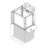
4.9 Electrical wiring
- Connect the wiring to the push-button board.
- Connect the electrical wiring of the double bottom (if
present).
- Connect the power supply cable provided to the circuit
breaker prepared previously.
- Insert the cable inside the corrugated cable hose
lead¬ing to the lift control panel (Fig. 31) and fi t the
connector as shown in (Fig. 33).
- Connect the cable to the panel in the positions shown
on the enclosed wiring diagrams.
- Connect the main sheath to the connectors provided,
remove the call control board and the lock, and connect
it to the sheath as shown in the diagram.
- Motor-operated gate: Wire the motor and sensor to the
main sheath (Fig. 32).
7512001