23
a
a
A
SEZ. A-A
A
15
a
b
7511020
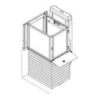
- Then proceed with coupling the two worm screws with
Ø 4 stop pin (Fig. 14).
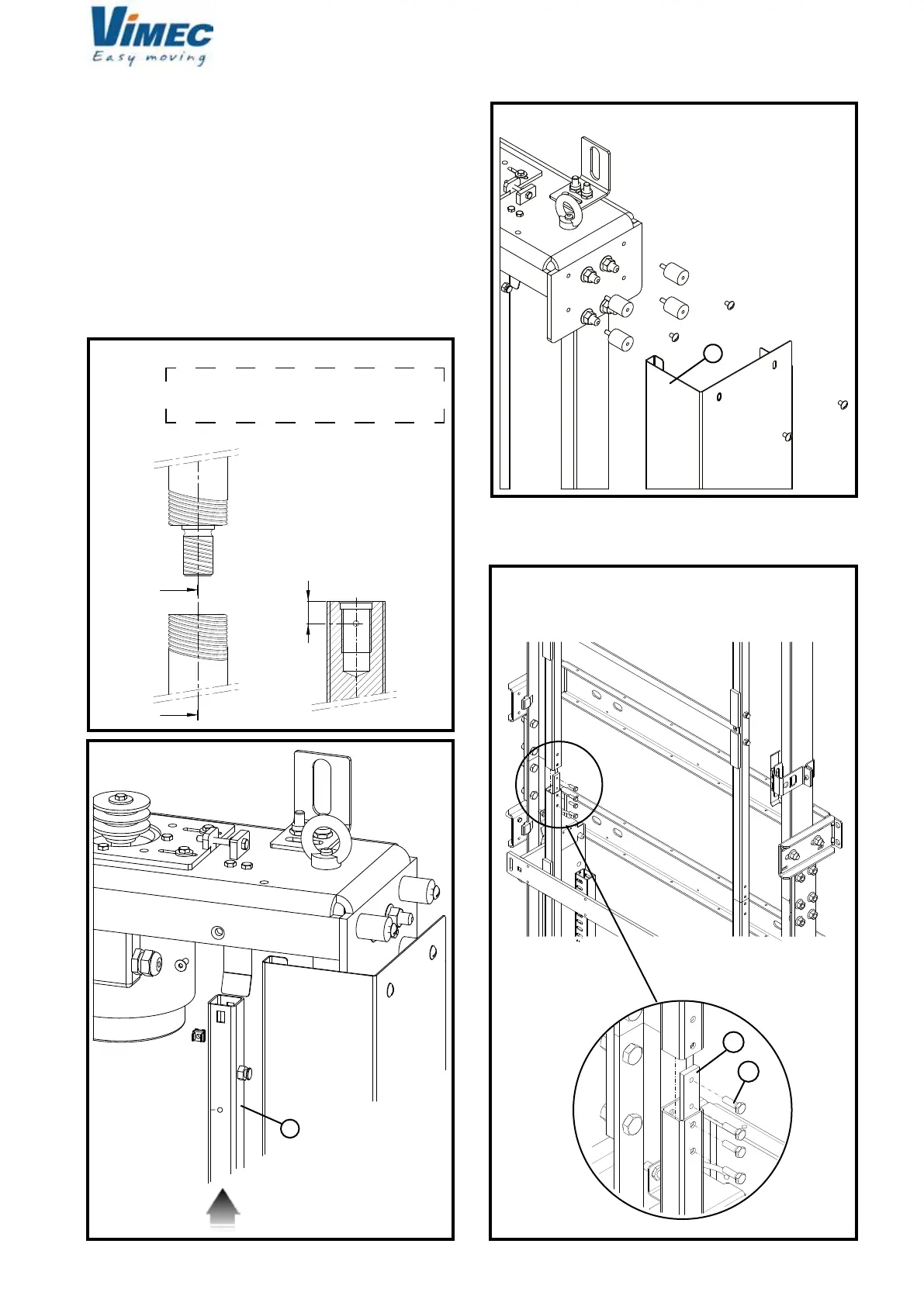
- Connect the two separated pipes using the special
joint plate provided (Fig. 17/a) and the screws ISO 4017
M6x20 (Fig. 17/b).
- After, proceed with assembling the front casing sup-
porting pipes and the cable through (Fig. 15/a).
- Lastly, assemble the rear and side casings (Fig. 16/a).
At this point, proceed with standard assembly (see
point 4).
FIG.14
Ø 4 hole for stop pin to be carried out with
coupled screws with 5 Nm tightening torque
and trapezoidal threads touching each other.
FIG.15
FIG.16
A - A SECT.
7512020
FIG.17
 Loading...